Fan blade

a technology of impeller blades and fan blades, which is applied in the direction of liquid fuel engines, vessel construction, marine propulsion, etc., can solve the problems of increasing the noise level thereby and the inability to completely remove the heat generated by the aforementioned electronic element, so as to achieve the effect of lowering the noise level

Active Publication Date: 2006-10-10
DELTA ELECTRONICS INC
View PDF4 Cites 11 Cited by
  • Summary
  • Abstract
  • Description
  • Claims
  • Application Information

AI Technical Summary

Benefits of technology

[0007]In view of the foregoing, it is an object of the present invention to provide an impeller applied to a centrifugal blower, so as to greatly lower the noise level while in operation.
[0008]The present invention further provides an impeller applied to a centrifugal fan, so as to greatly increase the air pressure in operation.
[0009]The present invention further provides an impeller applied to a centrifugal fan, so as to greatly increase the air flow in operation.
[0014]One portion of the fan blade of the impeller of the present invention has a windward side and a leeward side which are parallel to each other, and the other portion of the fan blade has the surfaces tangent to the aforementioned windward side and leeward side, so that the impeller of the present invention can introduce smoother and faster air flow than the conventional technology. Therefore, under the same operation conditions of air pressure and flow, the operation speed of the centrifugal fan with the impeller of the present invention is lower speed than that of the conventional technology, thus greatly lowering the noise level in operation.
[0015]The aforementioned fan blade of the impeller in the present invention has a larger windward side, so that, under the same operation condition of rotational speed, the centrifugal fan with the aforementioned impeller can achieve higher air pressure and more air flow than that with the conventional technology.

Problems solved by technology

However, when the rotational speed is increased, the noise level generated thereby raises correspondingly.
Although the noise level can be reduced by lowering the rotational speed of the conventional blower, the heat generated by the aforementioned electronic element can't be removed completely due to the less air flow and air pressure thereof.

Method used


Image

  • Fan blade
  • Fan blade
  • Fan blade

Examples


first example

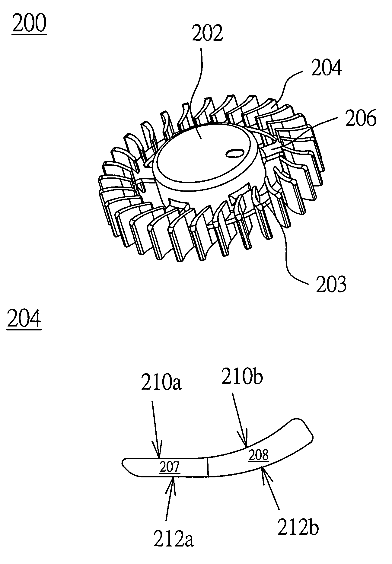
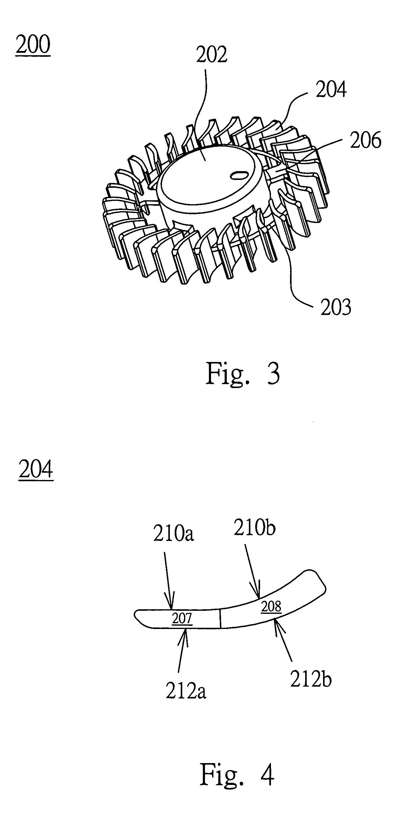
[0026]Referring to FIG. 3 to FIG. 5, FIG. 3 is a schematic diagram illustrating an impeller according to the first example in the preferred embodiment of the present invention, FIG. 4 is a front view of a fan blade 204; and FIG. 5 is a front view of the impeller 200. The impeller 200 has a hub 202, an annular part 203, fan blades 204, and a connection portion 206. The fan blades 204 are connected to the hub 202 via the connection portion 206, such as a rib.

[0027]The hub 202 includes a motor module used for driving the hub 202 to perform the motion of rotation. The annular part 203 surrounds the hub 202 and the annular part 203 is for disposing the fan blade 204 thereon. The connection portion 206 disposed between the annular part 203 and the hub 202 and the shape of the connection portion 206 can be such as a column shape, a radiation shape, an arc shape, the shape used in an axial-flow fan blade or a streamline shape, etc.

[0028]Each of the fan blades 204 is connected to the annular...

second example

[0032]Further, referring to FIG. 6, it is a schematic diagram illustrating an impeller 300 according to the second example in the preferred embodiment of the present invention. The difference between the impeller 300 and the aforementioned impeller 200 is that each of the fan blades 304 of the impeller 300 has a larger windward area than each of the fan blades 204 of the impeller 200. In this case, the end of each fan blade 304 on an annular part 303 can be at the location closer to the hub 302, so that greater air pressure, air flow and the better visual effect are obtained when the impeller 300 is applied to a centrifugal fan or a blower.

third example

[0033]Referring to FIG. 7, it is a schematic diagram illustrating an impeller 400 according to the third example in the preferred embodiment of the present invention. The difference between the impeller 400 and the aforementioned impeller 200 is that the impeller 400 further includes a base 406 located around the hub 402 and horizontally extended from the hub 402, and each of the fan blades 404 of the impeller 400 is vertically extended from the base 406 and on the base 406, or the fan blades 404 can be both vertically extended from the base 406 toward up and down, and the base 406 is considered as horizontally being in the middle of each fan blade 404. As to this type of impeller 400, the hub 402, the base 406 and the fan blades 404 can be integrally formed so as to reduce the process steps and thus shortening process time.


PUM


Abstract

An impeller is applied to a centrifugal fan and includes fan blades and a hub. Each fan blade includes a first portion and a second portion. The first portion is located relatively close to the hub and the first portion is coupled to the second portion. The first portion has a windward side and a leeward side, and the windward side is parallel to the leeward side. The second portion is located relatively far away from the hub. The second portion has a windward side and a leeward side, and the windward side and the leeward side are two curved surfaces with different specific curvatures.

Description

[0001]This Nonprovisional application claims priority under 35 U.S.C. § 119(a) on patent application Ser. No(s). 09 / 2,211,285 filed in TAIWAN on Jun. 20, 2003, the entire contents of which are hereby incorporated by reference.FIELD OF THE INVENTION[0002]The present invention relates to fan blades of an impeller, and more particularly to fan blades of an impeller in a centrifugal blower capable of greatly lowering the noise level.BACKGROUND OF THE INVENTION[0003]In a conventional system, since its internal electronic element is a large heat source, and the performance of the internal electronic element degrades with the increase of the temperature thereof, the heat generated thereby has to be quickly removed so as to keep the internal electronic element's regular performance. Therefore, a blower having high air pressure is commonly used to achieve the objective of rapidly dissipating heat.[0004]Conventionally, a fan with high air pressure is known as a centrifugal fan or blower. Plea...

Claims


Application Information

Patent Timeline
Patent Type & Authority Patents(United States)
IPC IPC(8): F04D29/30F04D29/28
CPCF04D29/282F04D29/30
Inventor WU, HSIU-WEICHEN, HENG-YILEE, CHIN-FULEE, WEN-TSAOHUANG, WEN-SHIHUANG, KUO-CHENHO, CHIEH-LUNG
Owner DELTA ELECTRONICS INC
Why Eureka
Try Eureka