Rotary process for forming uniform material
a technology of uniform material and rotary process, which is applied in the direction of synthetic resin layered products, weaving, bandages, etc., can solve the problems of inability to completely uniformize the web layer formed by these conventional flash spinning processes, and no existing process for collecting particles in a manner that preserves
- Summary
- Abstract
- Description
- Claims
- Application Information
AI Technical Summary
Benefits of technology
Problems solved by technology
Method used
Image
Examples
example 1
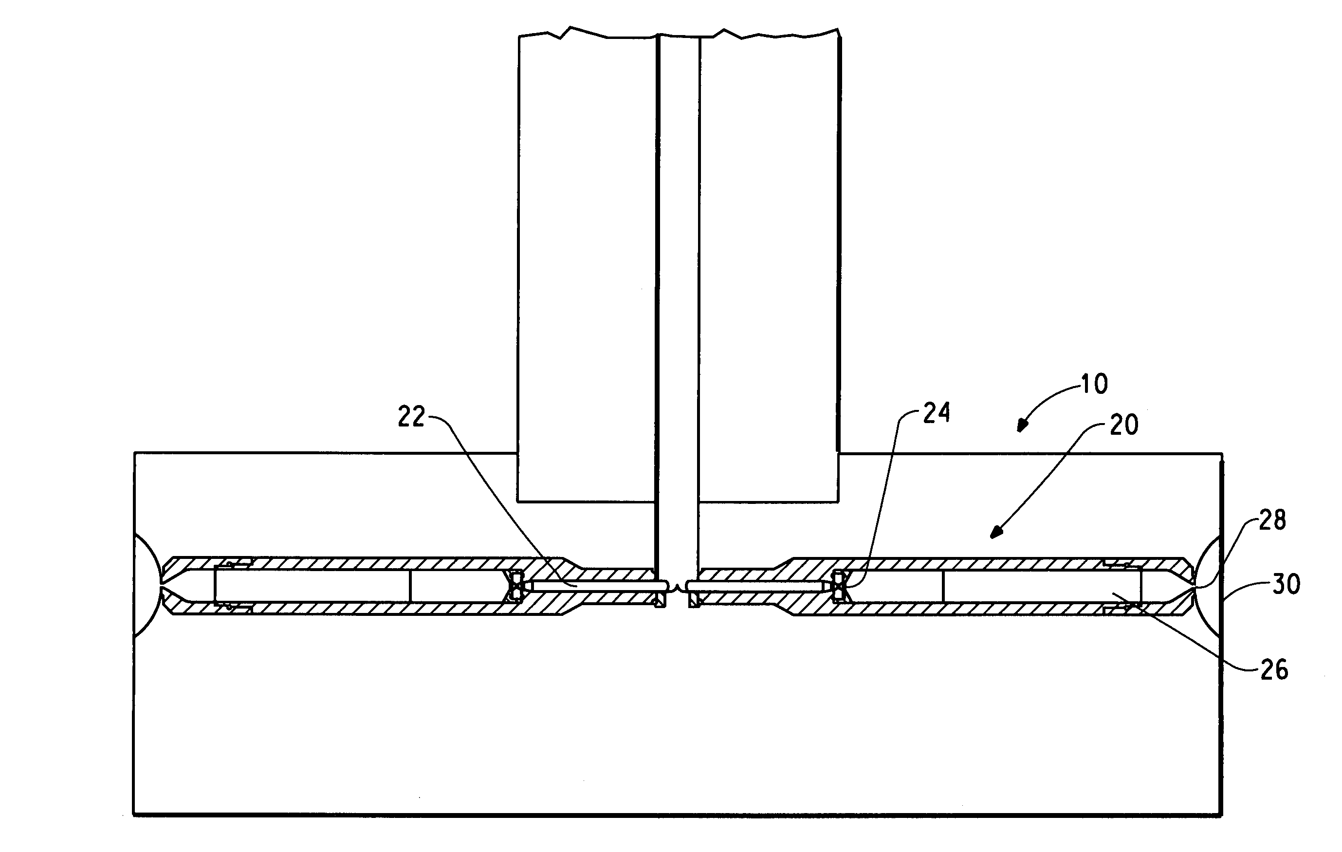
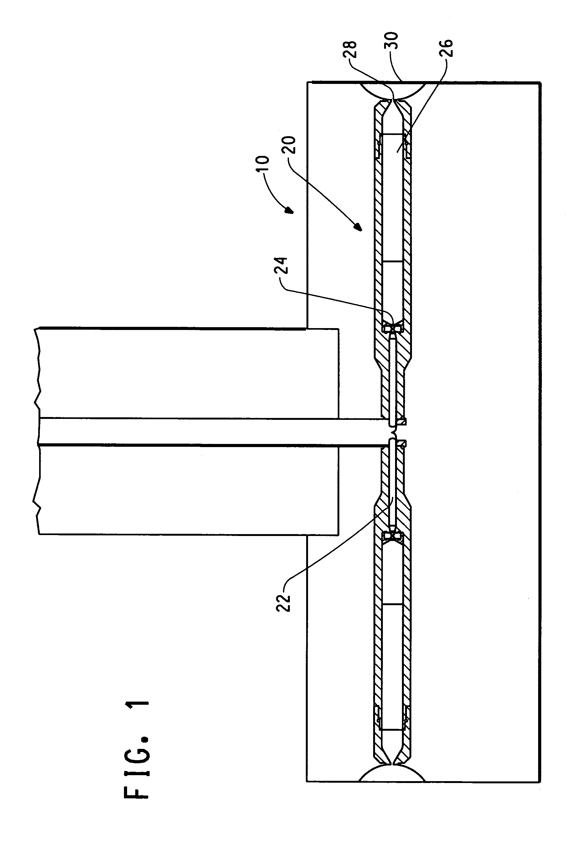
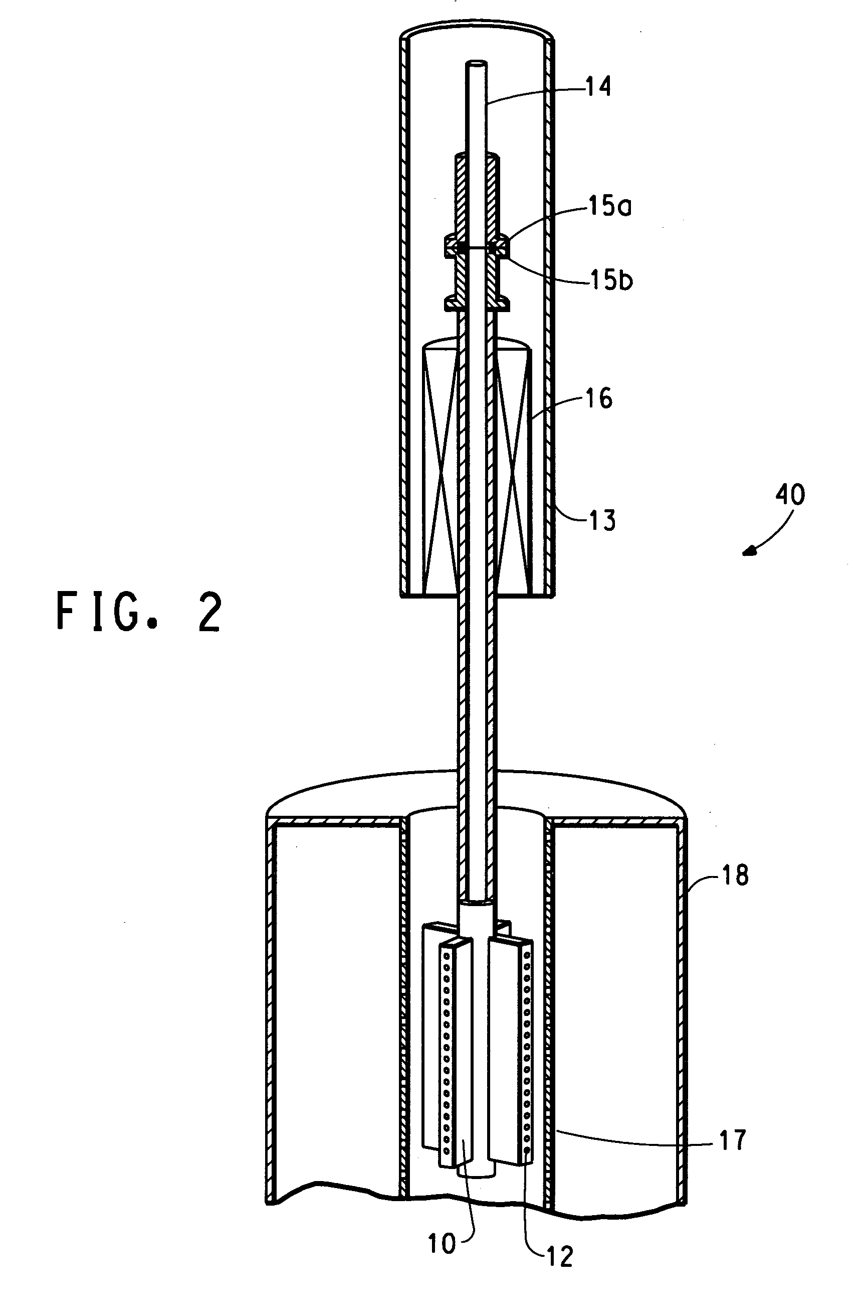
[0082]A polymeric solution of 1% Mat 8, Blue high density polyethylene (obtained from Equistar Chemicals LP) in a spin agent of Freon® 11 (obtained from Palmer Supply Company) at a temperature of 180° C. and a filter pressure of 2040 psi (14 MPa) was flash spun through a nozzle in a rotor having a diameter of 16 inches (41 cm) and a height of 3.6 inches (9.2 cm) rotating at 1000 rpm onto a leader sheet of white Sontara® fabric (available from E. I. du Pont de Nemours & Company, Inc.) on a porous collection belt. The outlet slot of the nozzle was oriented at a 30° angle away from the axis of the rotor. The flash spun material was discharged from the nozzle in the radial direction away from the rotor. The distance between the outlet of the nozzle and the collection belt was 1 inch (2.5 cm). The rotor was enclosed in a spin cell and the interior of the spin cell was maintained at a temperature of 50° C.
[0083]Electrostatic force was generated from 5 needles spaced evenly in a row just d...
example 2
[0086]A polymeric solution of 11% high density polyethylene (80% Mat 8 obtained from Equistar Chemicals LLP, having a melting temperature of about 138° C., and 20% Dow 50041 obtained from Dow Chemical, Inc., having a melting temperature of about 128° C.) in a spin agent of Freon® 11 (obtained from Palmer Supply Company) at a temperature of 190° C. and a filter pressure of 2030 psi (14 MPa) was flash spun through a nozzle in the rotor used in Example 1 rotating at 1000 rpm onto a belt of Reemay® Style 2014 fabric (obtained from Specialty Converting). The outlet slot of the nozzle was oriented axially to the rotor. The distance between the outlet of the nozzle and the collection belt was 1.5 inch (3.8 cm). The rotor was enclosed in a spin cell and the interior of the spin cell was maintained at a temperature of 125° C.
[0087]Vacuum was employed to assist with the pinning of the flash spun web to the collector.
[0088]An aerodynamic stainless steel foil extending 0.5 inch (1.3 cm) in the ...
example 3
[0090]A polymeric solution of 11% Mat 8 high density polyethylene in a spin agent of Freon® 11 (obtained from Palmer Supply Company) at a temperature of 190° C. and a filter pressure of 2110 psi (14 MPa) was flash spun through a nozzle in a rotor rotating at 158 rpm onto a belt of Sontara® 8010 fabric (available from E. I. du Pont de Nemours & Company, Inc.) moving at 5.4 yards per minute (4.9 m / min). The outlet slot of the nozzle was oriented axially to the rotor. The distance between the outlet of the nozzle and the collection belt was 1.5 inch (3.8 cm). The rotor was enclosed in a spin cell and the interior of the spin cell was maintained at a temperature of 120° C.
[0091]Electrostatic force and vacuum were employed simultaneously to assist with the pinning of the flash spun web to the collector. The electrostatic force in this example was generated from conductive brushes and from the serrated edge of the aerodynamic foil. Electrostatic brushes were installed on each end of the r...
PUM
| Property | Measurement | Unit |
|---|---|---|
| density | aaaaa | aaaaa |
| melting range | aaaaa | aaaaa |
| distance | aaaaa | aaaaa |
Abstract
Description
Claims
Application Information
 - R&D
- Intellectual Property
- Life Sciences
- Materials
- Tech Scout
- Unparalleled Data Quality
- Higher Quality Content
- 60% Fewer Hallucinations
Browse by: Latest US Patents, China's latest patents, Technical Efficacy Thesaurus, Application Domain, Technology Topic, Popular Technical Reports.
© 2025 PatSnap. All rights reserved.Legal|Privacy policy|Modern Slavery Act Transparency Statement|Sitemap|About US| Contact US: help@patsnap.com


