Heated hand grip

a hand grip and hand technology, applied in the field of heated hand grips, can solve the problems of inability to disclose a method for easily attaching a single hand grip to ski poles of varying sizes, the rod may inadvertently fall apart during use, and the difficulty of assembly or disassembly, so as to achieve the effect of convenient manufacture and easy installation

Inactive Publication Date: 2006-10-10
MEYERS MARCY
View PDF2 Cites 32 Cited by
  • Summary
  • Abstract
  • Description
  • Claims
  • Application Information

AI Technical Summary

Benefits of technology

[0007]An object of the instant invention is to provide a heated hand grip that can be easily installed on a ski pole or other tubular object. Another object of the instant invention is to provide a heated hand grip that provides a comfortable, cushioned grip. Other objects of the instant invention are to provide an electrically heated hand grip that is waterproof, easy to manufacture, lightweight and reliable.
[0009]In a preferred embodiment of the instant invention, the outer surface of the central core is generally smooth and a wire-wound heating element (including a fiberglass material backing and an electrical conductor) is wrapped around and attached to the smooth surface. In an alternative embodiment, the outer surface of the central core includes helical grooves in which a wire heating element is positioned. The heating element is connected to the PCB to be turned on and off by the control switch. The central core is manufactured of a relatively rigid material, such as high density polypropylene (HDPP). In a preferred embodiment the central core is made of a composite of HDPP which includes approximately 30% glass. The glass increases the insulating characteristics of the central core so as to minimize heat drain from the heating element to the bore of the central core and through the pole to which the grip is attached.
[0010]The one-piece pour-over outer housing forms a shell around the outer surface of the central core of the hand grip. The housing is made of a rubber, lower density polypropylene, or other material suitable to provide the amount of cushioning desired for the hand grip. The material, in a fluid state, is poured over the central core after the heating element is positioned (either over the smooth surface or in the grooves of the core), and the fluid is allowed to solidify. In the embodiment in which the heating element comprises a fiber glass backing material and attached conductor, the fluid of the housing pour-over will soak through the fiberglass backing to bond with the central core. The thicknesses of the walls of the outer housing are minimized to increase the efficiency of heat conduction from the heating element to the outer surface of the housing. At the same time enough wall thickness is provided to provide adequate cushioning for the grip when held by a user.
[0011]In a preferred embodiment, appropriate material compositions and thickness are selected to allow the outer surface of the outer housing to reach and maintain a temperature of 104° F. at an environmental temperature as low as −20° F. A temperature sensor (or temperature limiter switch) is located between the outer surface of the central core and the inner surface of the housing. The temperature sensor is connected electrically to the PCB to cause the heating element to be deenergized when the temperature exceeds the 104° F. level. In addition, the temperature sensor will cause the heating element to reenergize when the temperature drops below a minimum level, such as 95° F. It will be appreciated that two or more separate temperature switches can also be utilized to maintain the temperature in the desired operating range.
[0012]In a preferred embodiment of the instant invention, a split bushing is utilized to hold the ski pole within the bore of the central core. In addition, the lower portions of the central core and the outer housing, in which the bushing is to be located, include a lateral slit. The split bushing allows the ski pole to be easily inserted into the bushing by reducing the frictional forces exerted on the outer surface of the pole by the inner surface of the bushing as the split in the bushing allows the walls of the bushing to deform and separate from each other as the pole is inserted. Likewise, the lateral slit in the core / housing allows the walls of the core / housing to separate from each other as the bushing is inserted into the bore, allowing the bushing to be inserted with a minimal amount of effort. Once the ski pole is inserted in the bushing the bushing then is inserted in the bore of the central core (to which the outer housing has already been poured over). A screw is then inserted through the housing / core and tightened to clamp the housing / core around the bushing, which in turn clamps the bushing around the pole. This provides a tight frictional fit between all of the components such that the pole cannot be released from the hand grip without loosening the screw. In a preferred embodiment, multiple bushings having various inner diameters are provided with each hand grip to allow the hand grip to be installed on ski poles of varying common outer diameters. For example, common outer diameters for ski poles include, but are not limited to, 13 mm and 11 mm. The actual diameters for a ski pole shaft will vary slightly between manufacturers and materials used for the pole. Nevertheless, the construction of the instant invention including the split bushing, core slit and screw allows for a tight frictional engagement regardless of slight variations in pole diameters. Therefore, it is not required that the bushing of the instant invention have an inner diameter that corresponds exactly to the outer diameter of the pole. Bushings of various other inner diameters can be utilized in connection with the instant invention to permit installation on virtually any tubular object in which inclement conditions affect warmth and comfort, such as alpine poles, hiking poles, cross country poles, shovels, paddles, etc. Furthermore, it will be appreciated that the bushing can be eliminated in cases in which the inner diameter of the bore in the central core corresponds to the outer diameter of the tubular object to which the handle is being attached, and multiple size options are not desired. For example, the hand grip of the instant invention can be designed to be the handle for a snow shovel. In such an arrangement, slight modification of the hand grip discussed above will be made to retain the battery in position without the bushing.

Problems solved by technology

If the coefficient of friction is too low, or the tolerance between outer and inner surfaces is too high, the rod may inadvertently come apart during use.
If the coefficient of friction is too high, or the tolerance between outer and inner surfaces is too low, assembly or disassembly will be more difficult.
Although Adamson states that the hand grip can be held in place on the ski pole by a variety of methods, such as an interference fit, a mechanical locking arrangement or an adhesive, Adamson does not disclose a method for easily attaching a single hand grip to ski poles of varying sizes.
While such an arrangement is acceptable for the hand grip of Adamson, in which the heating element is located on the interior surface of a protective shield than surrounds the portion of the hand grip that is held within the skier's hand, it is less desirable for hand grips in which the source of heat is intended to emanate from the portion of the grip being held with the skier's hand.
In such instances, the location of a heating element on the surface of the grip or formed integrally with the surface of the grip will greatly limit the materials that may be utilized to provide a comfortable, cushioned grip.

Method used


Image

  • Heated hand grip
  • Heated hand grip
  • Heated hand grip

Examples


Embodiment Construction

[0030]As required, detailed embodiments of the present invention are disclosed herein; however, it is to be understood that the disclosed embodiments are merely exemplary of the principles of the invention, which may be embodied in various forms. Therefore, specific structural and functional details disclosed herein are not to be interpreted as limiting, but merely as a basis for the claims and as a representative basis for teaching one skilled in the art to variously employ the present invention in virtually any appropriately detailed structure.

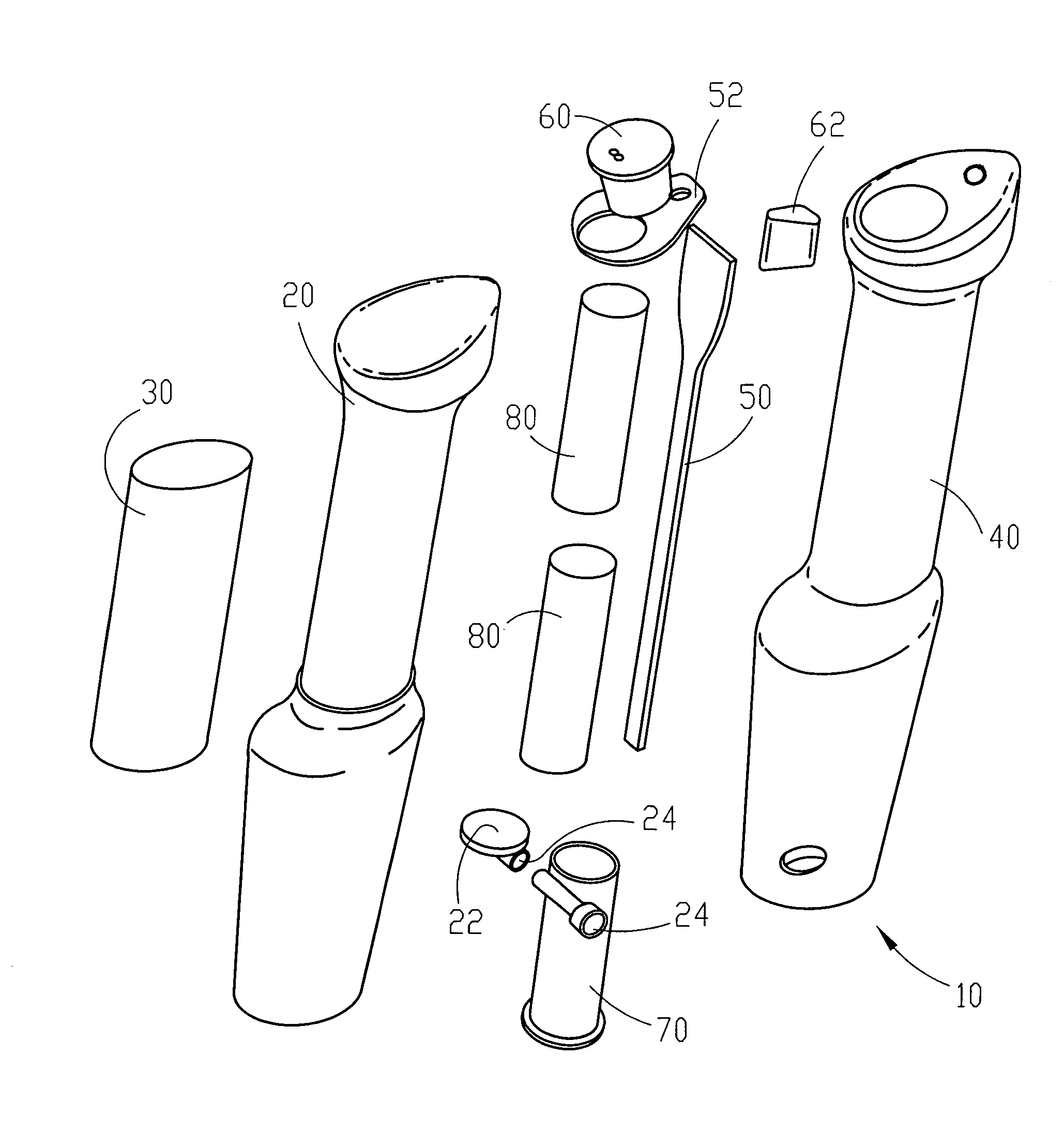
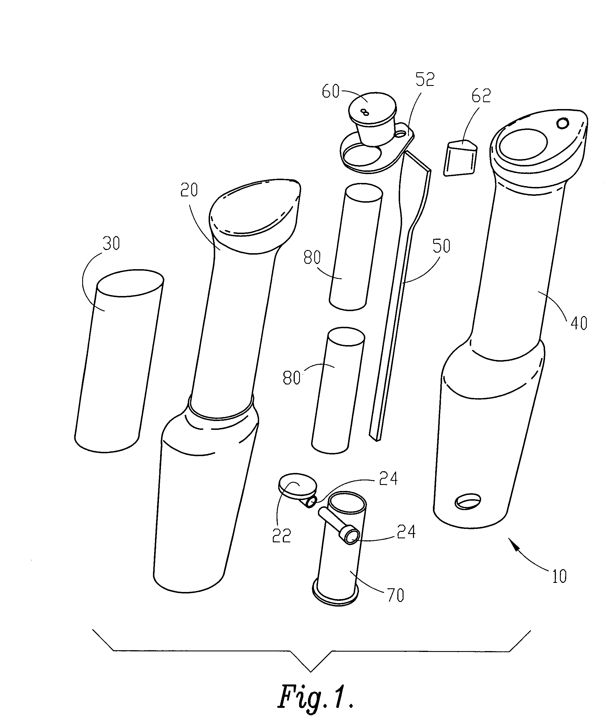
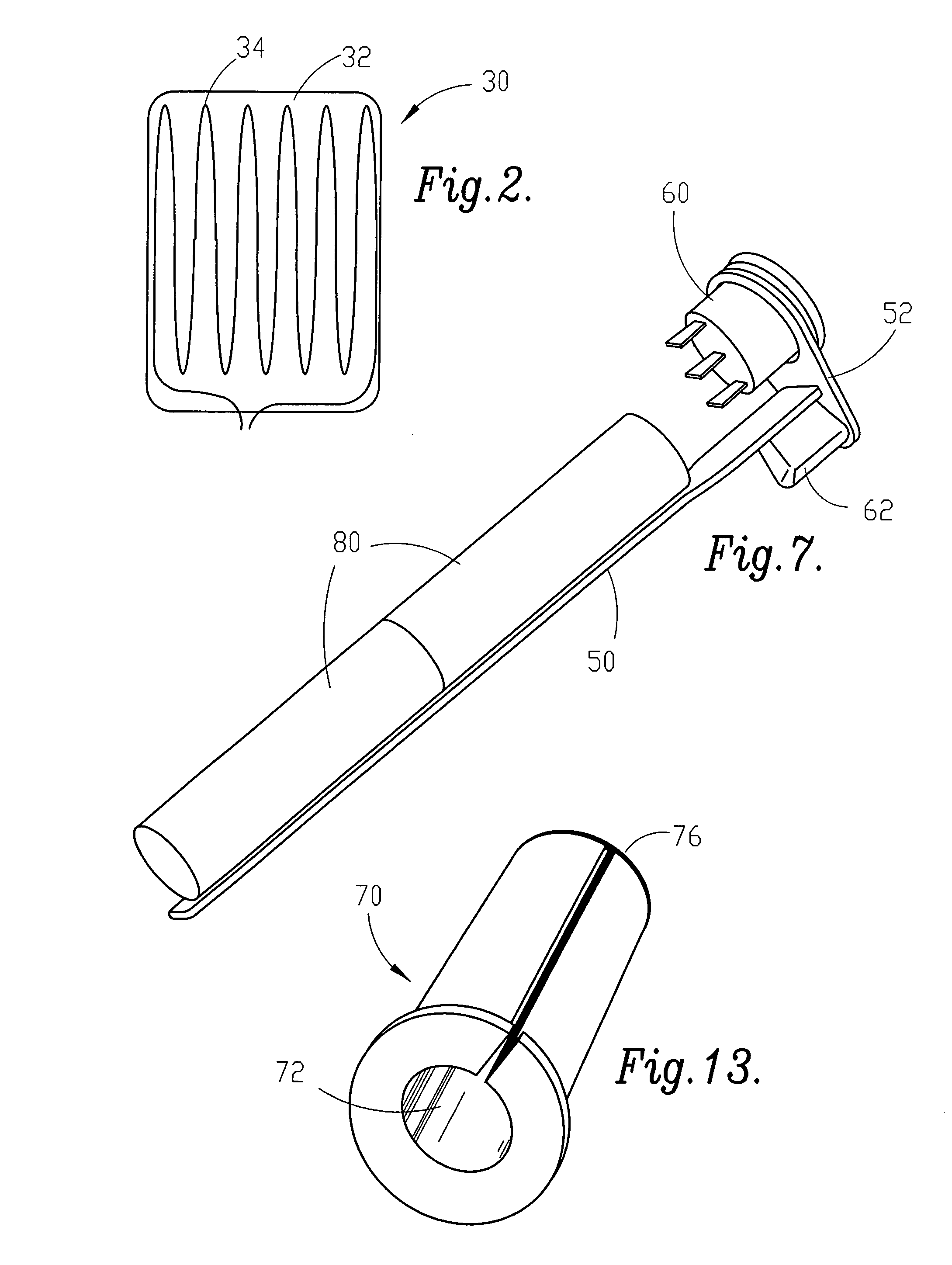
[0031]Referring to FIGS. 1 through 8, a preferred embodiment of a heated hand grip of the instant invention for use on a ski pole is shown and described. FIG. 1 shows an exploded view of hand grip 10 which includes central core 20, set-screw assembly 24, battery core pad 22, heating element 30, outer housing 40, printed circuit boards 50 and 52, push button control switch 60, DC charger jack 62, bushing 70, and two (2) batteries 80. In the e...


PUM


Abstract

A rechargeable, reusable heated hand grip for use on a ski pole, shovel or other cold weather hand-held tool or object is provided. The hand grip includes a bushing for receiving the end of a tubular object and retaining the object within a bore in the central core of the hand grip, which compresses around the bushing for tight engagement. A wire-wound heating element is wrapped around the exterior surface of the central core and an outer housing surrounds the heating element and the central core. The bore houses a pair of lithium-ion batteries connected in series, a switch with the switch control protruding from the top of the grip, and a printed circuit board connected to the switch.

Description

[0001]This application claims priority pursuant to 35 U.S.C. 119(e) to co-pending U.S. Provisional Patent Application Ser. No. 60 / 604,585, filed Aug. 26, 2004, the entire disclosure of which is incorporated herein by reference.FIELD OF THE INVENTION[0002]The present invention relates generally to a heated hand grip. More particularly, the present invention is concerned with a heated hand grip for use on a ski pole, shovel or other cold weather hand-held tool or object.BACKGROUND OF THE INVENTION[0003]Heated hand grips for cold weather hand-held objects, such as ski poles, archery bows, fishing poles and trolling motors are well known. Examples of such heated hand grips are shown in U.S. Pat. No. 4,440,421 issued to Adamson, U.S. Pat. No. 4,598,192 issued to Garrett, U.S. Pat. No. 5,585,026 issued to Smith, Jr. et al., and U.S. Pat. No. 5,934,267 issued to Briner, the entire disclosures of which are incorporated herein by reference.[0004]The disclosures of Briner and Smith, Jr. et al...

Claims


Application Information

Patent Timeline
Patent Type & Authority Patents(United States)
IPC IPC(8): H05B1/00
CPCA63C11/222A63C2203/12
Inventor MEYERS, MARCY
Owner MEYERS MARCY
Why Eureka
Try Eureka