Electronic tampering detection system

a detection system and electronic technology, applied in the direction of burglar alarm mechanical actuation, locking devices, instruments, etc., can solve problems such as changes in electrical characteristics of primary circuits, and achieve the effect of increasing light exposur

Inactive Publication Date: 2006-10-10
INTELLIGENT DEVICES SEZC
View PDF7 Cites 18 Cited by
  • Summary
  • Abstract
  • Description
  • Claims
  • Application Information

AI Technical Summary

Benefits of technology

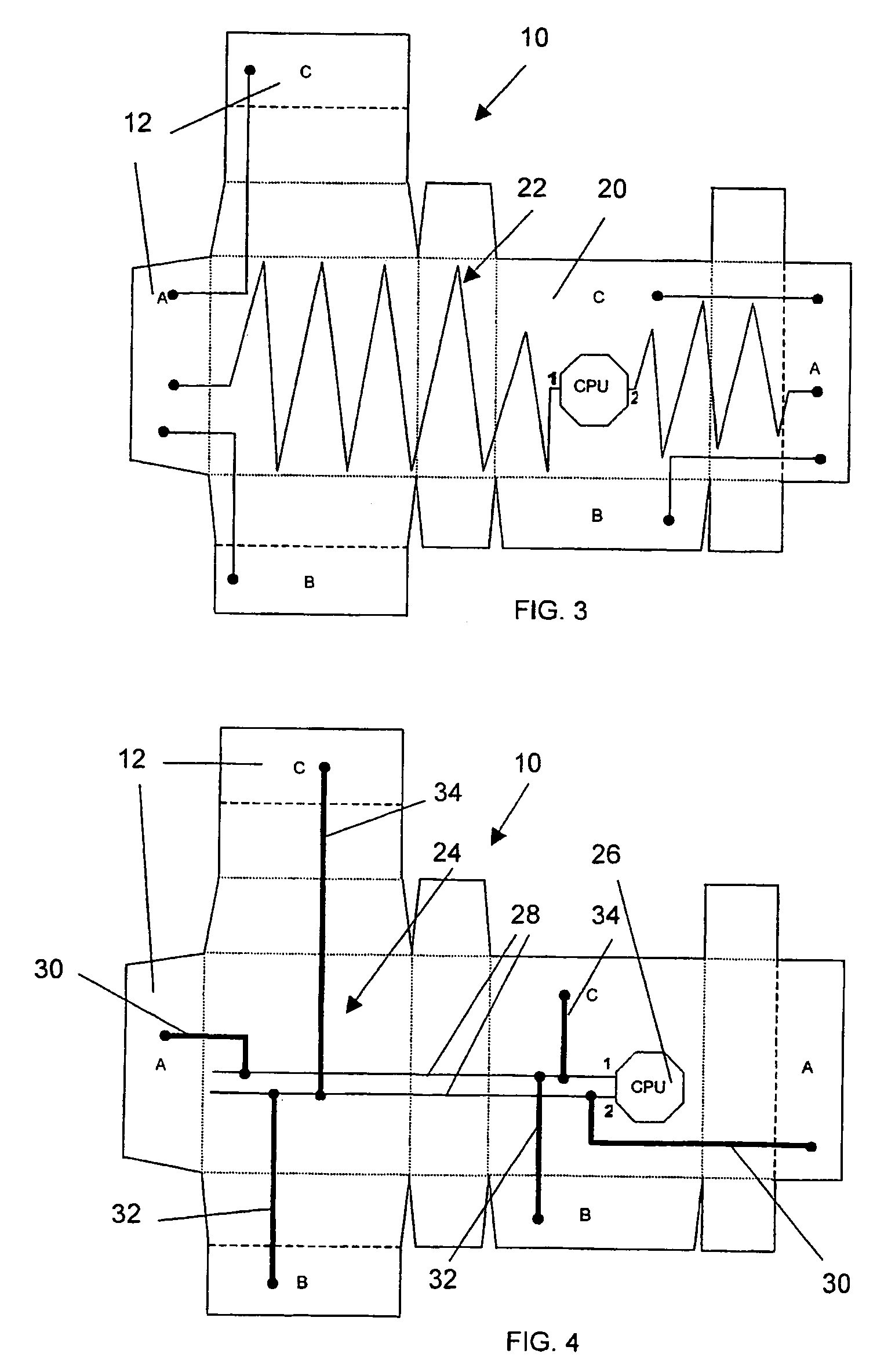
[0008]The second method uses one or a plurality of sensor circuits arranged as resistances in parallel in a primary circuit, the electrical characteristics of which are monitored by the CPU via an analog-to-digital converter (ADC). Interrupting the continuity of the sensor circuits results in changes in the electrical characteristics of the primary circuit. Changes are compared to fixed (or dynamic) change criteria stored (or calculated) in the CPU's procedure memory and those changes meeting the criteria are interpreted as tampering and / or penetration events. The criteria for a significant change may be fixed at the time of programming the CPU, or they could be dynamic, where the procedure memory of the CPU updates the change criteria on the basis of its most recent determinations. The use of dynamic criteria compensates for drifting of the electrical characteristics of the circuit such as those due to changes in temperature and humidity, which changes do not vary linearly as a function of the number of events previously detected. The use of dynamic criteria maximizes the discriminability of the changes in resistance occasioned by breaking the sensor circuits, permitting more such sensor circuits to be monitored by a single circuit of given voltage. The time and other characteristics of interest are then stored in the CPU's data memory for later retrieval by an interested party. Because this method is based on a number of values or steps in the electrical characteristics of a circuit it can be described as an “analog” method.
[0021]The use of a CPU with an ADC allows for the use of other environmental sensors in conjunction with the monitoring system described above. Sensors to measure changes in light, orientation, temperature, radiation, humidity and pressure can be used to supplement the tamper detecting ability of the present invention. For example, dark packages can be monitored by the ADC for increased light exposure; vacuum sealed packages can be monitored for changes in pressure; refrigerated packages can be monitored for changes in temperature as means of detecting tampering.

Problems solved by technology

Interrupting the continuity of the sensor circuits results in changes in the electrical characteristics of the primary circuit.

Method used


Image

  • Electronic tampering detection system
  • Electronic tampering detection system
  • Electronic tampering detection system

Examples


Embodiment Construction

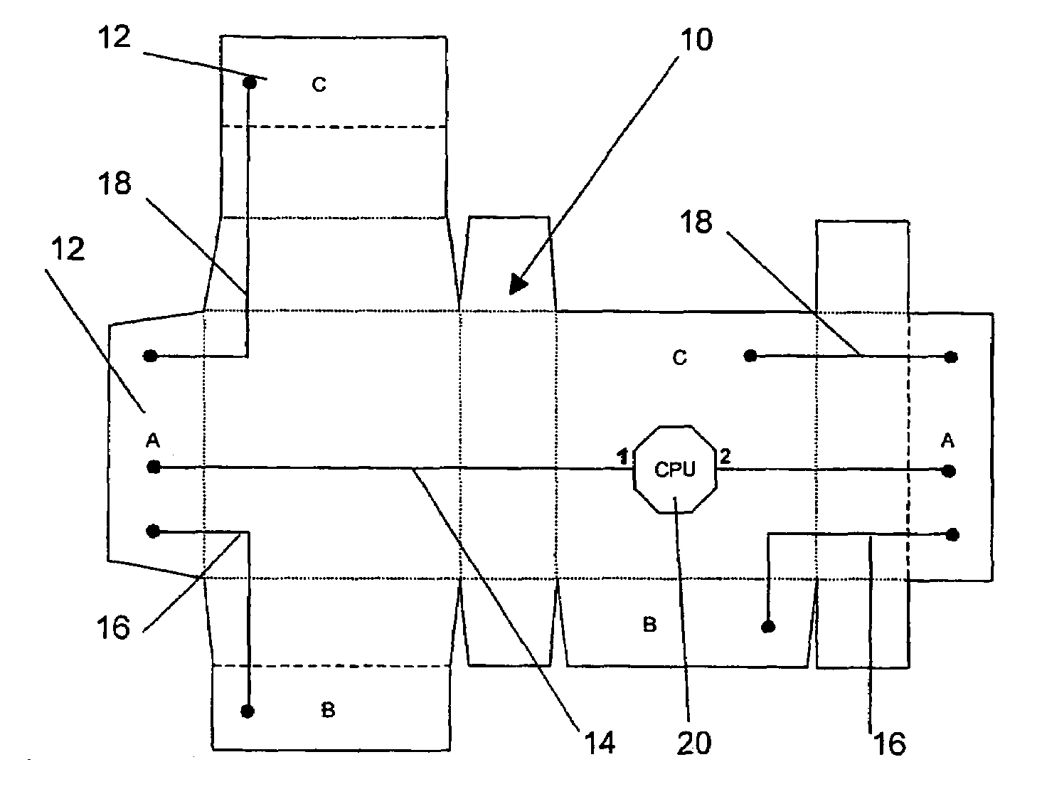
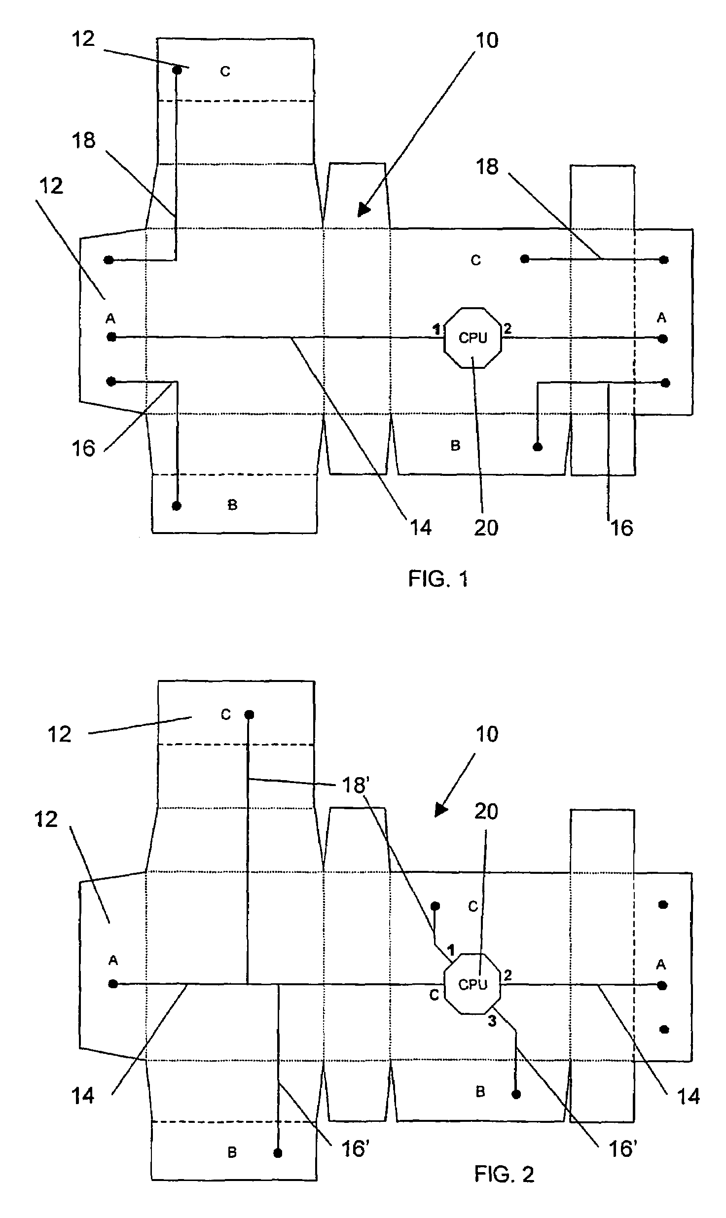
[0036]Referring to FIG. 1, a digital tampering detection device is described in accordance with an embodiment of the present invention, which device can be integrated in any paper board (cardboard) package during manufacturing. Typically, the package will be formed from a blank 10 provided with at least a pair of closure tabs which are adhesively secured together to close the blank, after folding into a closed package. In the embodiments shown the blank includes pairs of closure tabs A—A; B—B; and C—C which will co-act with each other to close the package. In the application depicted in FIG. 1, the device is arranged to detect unauthorized opening of a package (tampering) via the package's closing tabs.

[0037]The tamper detection system requires the closing tabs of the package (A—A, B—B and C—C in FIG. 1) to be coated with electrically conductive adhesive 12. A system of electrically conducting traces 14, 16, 18 of ink or other material is printed or otherwise applied to the surface ...


PUM


Abstract

An electronic tampering detection system is applied to a blank which can be formed into a package through the use of closure tabs which are coated with an electrically conductive adhesive. An electronic chip or CPU is applied to the blank and electrically conductive traces are printed or otherwise formed on the blank to connect the CPU to a first pair of the closure tabs to form an electric circuit. Other traces on the blank connect the first pair of closure tabs to the other closure tabs to form an enlarged circuit. The CPU has procedure memory, data memory, a power source, a clock and communication means associated therewith. If a package is opened accidentally or intentionally before it should be opened by way of the closure tabs the electric circuit is broken and a time stamp from the CPU clock is stored in the data memory for later retrieval. The circuit can be formed as resistances in parallel and an analog to digital converter can be used to provide an appropriate signal to the CPU. The electric circuit can cover a large portion of the blank's surface to provide a signal in the event of unauthorized penetration of the formed package.

Description

[0001]This application is a continuation of, and claims the benefit of, International Application No. PCT / CA2003 / 001625, filed 24 Oct. 2003 and entitled “Electronic Tampering Detection System”, published in English on 6 May 2004 under Publication No. WO 2004 / 037660 A1, the disclosure of which is hereby incorporated herein by reference. This application also claims the benefit of Canada Serial No. 2,409,624, filed 25 Oct. 2002.[0002]This invention relates to a system for detecting tampering with paper board (cardboard) packages and containers.BACKGROUND OF THE INVENTION[0003]Folded paper board (cardboard) packages (boxes, containers) are widely used to organize and ship a variety of contents. Many such contents are at risk for tampering or theft. In such scenarios, the paper board package is opened by an unauthorized person, giving unauthorized access to the contents of the package. The contents may be stolen and replaced with inactive versions of the contents, part or all of the uni...

Claims


Application Information

Patent Timeline
Patent Type & Authority Patents(United States)
IPC IPC(8): G08B13/14B65D5/42B65D55/02G06K19/073G08B13/12
CPCB65D5/42B65D55/028G06K19/073G06K19/07798G08B13/126B65D2101/00B65D2211/00B65D2401/00
Inventor PETERSENWILSON, ALLAN
Owner INTELLIGENT DEVICES SEZC
Why Eureka
Try Eureka