Transmitter diversity technique for wireless communications
What is Al technical title?
Al technical title is built by PatSnap Al team. It summarizes the technical point description of the patent document.
a technology of wireless communication and transmitter, applied in the field of wireless communication, can solve the problems of power by x db, transmission repeat, and transmission dynamic rang
Inactive Publication Date: 2006-10-10
AT&T MOBILITY II LLC
View PDF107 Cites 30 Cited by
Summary
Abstract
Description
Claims
Application Information
AI Technical Summary
This helps you quickly interpret patents by identifying the three key elements:
Problems solved by technology
Method used
Benefits of technology
[0010]The problems of prior art systems are overcome, and an advance in the art is realized with a simple block coding arrangement where symbols are transmitted over a plurality of transmit channels and the coding comprises only of simple arithmetic operations, such as negation and conjugation. The diversity created by the transmitter utilizes space diversity and either time diversity or frequency diversity. Space diversity is effected by redundantly transmitting over a plurality of antennas; time diversity is effected by redundantly transmitting at different times; and frequency diversity is effected by redundantly transmitting at different frequencies. Illustratively, using two transmit antennas and a single receive antenna, one of the disclosed embodiments provides the same diversity gain as the maximal-ratio receiver combining (MRRC) scheme with one transmit antenna and two receive antennas. The novel approach does not require any bandwidth expansion or feedback from the receiver to the transmitter, and has the same decoding complexity as the MRRC. The diversity improvement is equal to applying maximal-ratio receiver combining (MRRC) at the receiver with the same number of antennas. The principles of this invention are applicable to arrangements with more than two antennas, and an illustrative embodiment is disclosed using the same space block code with two transmit and two receive antennas. This scheme provides the same diversity gain as four-branch MRRC.
Problems solved by technology
However, there are two fundamental problems with this approach.
The first problem is the transmitter's dynamic range.
For the transmitter to overcome an x dB fade, it must increase its power by x dB which, in most cases, is not practical because of radiation power limitations, and the size and cost of amplifiers.
The second problem is that the transmitter does not have any knowledge of the channel as seen by the receiver (except for time division duplex systems, where the transmitter receives power from a known other transmitter over the same channel).
Therefore, if one wants to control a transmitter based on channel characteristics, channel information has to be sent from the receiver to the transmitter, which results in throughput degradation and added complexity to both the transmitter and the receiver.
However, time interleaving results in unnecessarily large delays when the channel is slowly varying.
Equivalently, frequency diversity techniques are ineffective when the coherence bandwidth of the channel is large (small delay spread).
The major problem with using the receiver diversity approach in current wireless communication systems, such as IS-136 and GSM, is the cost, size and power consumption constraints of the receivers.
The addition of multiple antennas and RF chains (or selection and switching circuits) in receivers is presently not be feasible.
Method used
Image
Click on the blue label to locate the original text in one second.
Reading with bidirectional positioning of images and text.
Examples
Embodiment Construction
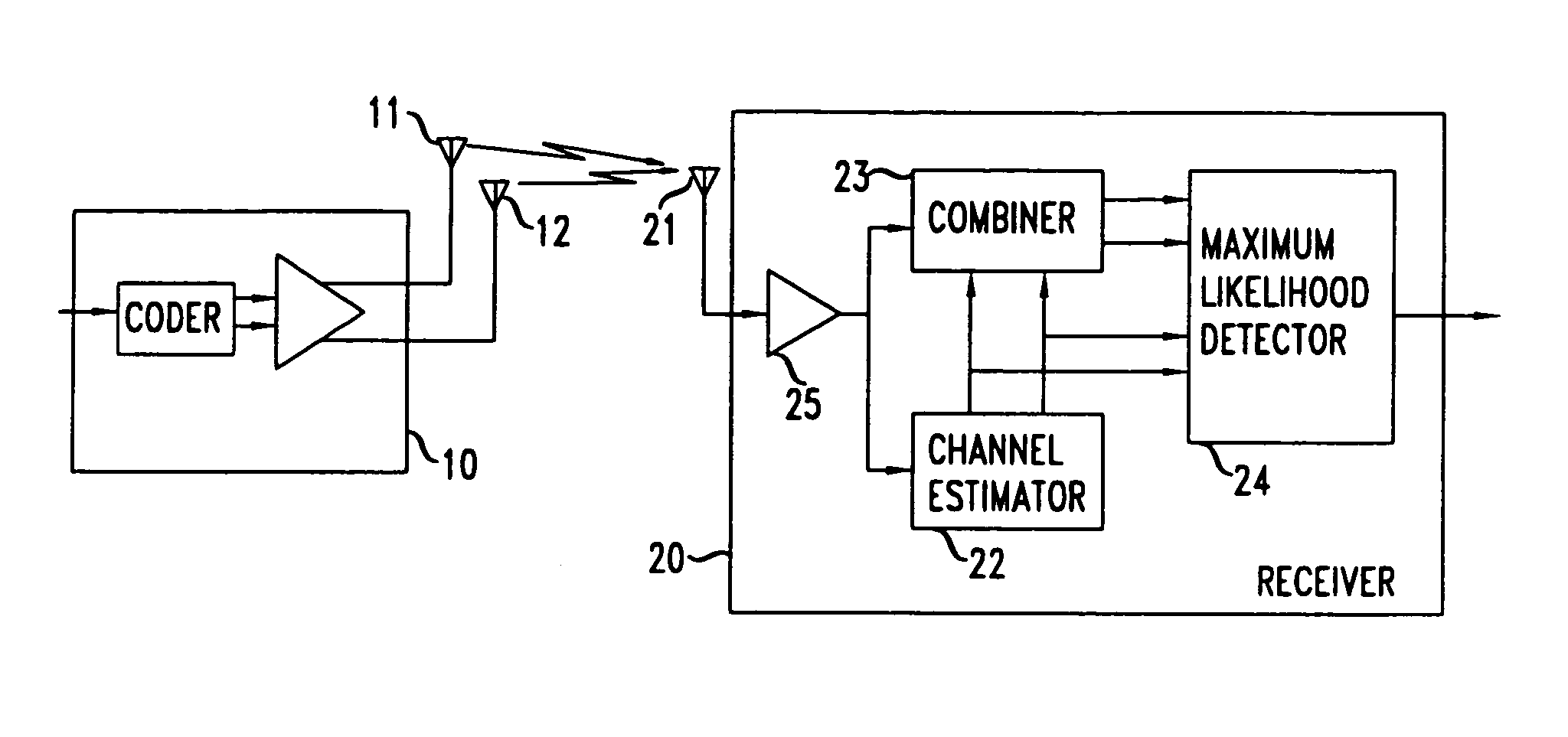
[0015]In accordance with the principles of this invention, effective communication is achieved with encoding of symbols that comprises merely negations and conjugations of symbols (which really is merely negation of the imaginary part) in combination with a transmitter created diversity. Space diversity and either frequency diversity or time diversity are employed.
[0016]FIG. 1 presents a block diagram of an arrangement where the two controllable aspects of the transmitter that are used are space and time. That is, the FIG. 1 arrangement includes multiple transmitter antennas (providing space diversity) and employs multiple time intervals. Specifically, transmitter 10 illustratively comprises antennas 11 and 12, and it handles incoming data in blocks n symbols, where n is the number of transmitter antennas, and in the illustrative embodiment of FIG. 1, it equals 2, and each block takes n symbol intervals to transmit. Also illustratively, the FIG. 1 arrangement includes a receiver 20 ...
PUM
Abstract
A simple block coding arrangement is created with symbols transmitted over a plurality of transmit channels, in connection with coding that comprises only of simple arithmetic operations, such as negation and conjugation. The diversity created by the transmitter utilizes space diversity and either time or frequency diversity. Space diversity is effected by redundantly transmitting over a plurality of antennas, time diversity is effected by redundantly transmitting at different times, and frequency diversity is effected by redundantly transmitting at different frequencies. Illustratively, using two transmit antennas and a single receive antenna, one of the disclosed embodiments provides the same diversity gain as the maximal-ratio receiver combining (MRRC) scheme with one transmit antenna and two receive antennas. The principles of this invention are applicable to arrangements with more than two antennas, and an illustrative embodiment is disclosed using the same space block code with two transmit and two receive antennas.
Description
REFERENCE TO RELATED APPLICATIONS[0001]This application is a continuation of U.S. patent application Ser. No. 09 / 730,151, filed Dec. 5, 2000 (now U.S. Pat. No. 6,775,329, which is a continuation of U.S. patent application Ser. No. 09 / 074,224, filed May 7, 1998 (now U.S. Pat. No. 6,185,258 issued Feb. 6, 2001); and this application claims the benefit of U.S. Provisional Application No. 60 / 059,016, filed Sep. 16, 1997; of U.S. Provisional Application No. 60 / 059,219, filed Sep. 18, 1997; and of U.S. Provisional Application No. 60 / 063,780, filed Oct. 31, 1997, all of which are hereby incorporated by reference.BACKGROUND OF THE INVENTION[0002]This invention relates to wireless communication and, more particularly, to techniques for effective wireless communication in the presence of fading and other degradations.[0003]The most effective technique for mitigating multipath fading in a wireless radio channel is to cancel the effect of fading at the transmitter by controlling the transmitter...
Claims
Application Information
Patent Timeline
Application Date:The date an application was filed.
Publication Date:The date a patent or application was officially published.
First Publication Date:The earliest publication date of a patent with the same application number.
Issue Date:Publication date of the patent grant document.
PCT Entry Date:The Entry date of PCT National Phase.
Estimated Expiry Date:The statutory expiry date of a patent right according to the Patent Law, and it is the longest term of protection that the patent right can achieve without the termination of the patent right due to other reasons(Term extension factor has been taken into account ).
Invalid Date:Actual expiry date is based on effective date or publication date of legal transaction data of invalid patent.