
Blister pack

a technology of aluminum foil and perforation line, which is applied in the direction of tray containers, ampoules, containers, etc., can solve the problems and achieve the effect of further increase in the chance of aluminum foil being ripped along the perforation lin

Active Publication Date: 2006-10-17
ROMACO PHARMATECHN
View PDF8 Cites 41 Cited by
  • Summary
  • Abstract
  • Description
  • Claims
  • Application Information

AI Technical Summary

Benefits of technology

[0010]It has been found that, if the perforation line extends along the seal edge, essentially no rip wedges are formed. As a result, in an advantageous manner, the distance between the seal-free area and the respective chamber does not need to be large. Furthermore, the area may have any shape; it may be round, triangular or rectangular. This has the advantage that the blister pack according to the invention can be very small.
[0011]It is furthermore very advantageous that no or only very small rip wedges are formed so that the possibility of damaging, the closure of one of the chambers is remote or even non-existent.
[0012]It has been found to be very advantageous if the perforations are provided during the connection of the aluminum foil to the base foil. In this way, the chances that the aluminum foil is ripped along the perforation line are further increased. The reason herefor may reside in the fact that the perforations are established at a point in time when the aluminum foil is not yet fully connected to the base foil.

Problems solved by technology

In this way, the chances that the aluminum foil is ripped along the perforation line are further increased.

Method used


Image

  • Blister pack
  • Blister pack

Examples


Embodiment Construction

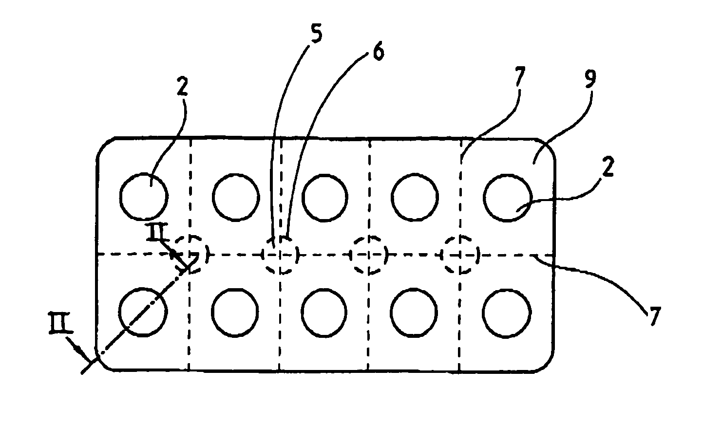
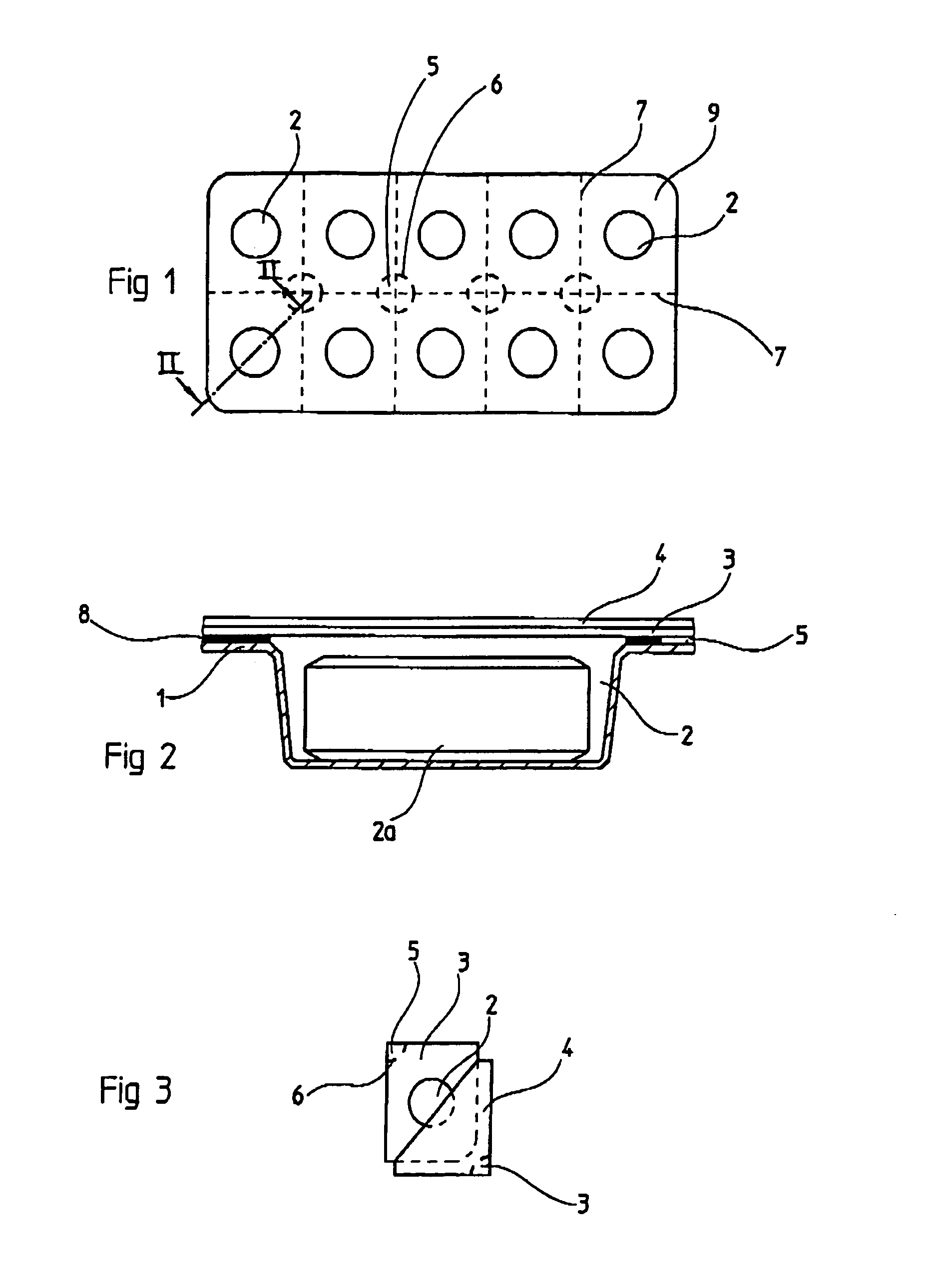
[0017]The blister pack shown in FIG. 1 includes ten chambers 2 which are arranged each in an area 9 of the blister pack divided by perforation lines 7.

[0018]As shown in FIG. 2, the blister pack consists of a base foil 1 into which chambers 2 are formed by a cupping procedure and in which a product 2a is contained.

[0019]The chambers 2 are covered by a rupture foil 3 of aluminum. The aluminum foil 3 is attached to the base foil 1 by heating of a hot seal lacquer 8 which is disposed between the base foil 1 and the aluminum foil 3.

[0020]On the aluminum foil 3, that is, on the side thereof, remote from the base foil 1, a removable plastic foil 4 is disposed.

[0021]The attachment force with which the plastic foil 4 is connected to the aluminum foil 3 is smaller than the attachment force holding the aluminum foil to the base foil 1. As a result, the plastic foil 4 can be removed from the aluminum foil 3 while the aluminum foil remains firmly connected to the base foil 1.

[0022]As shown in FI...


PUM

PropertyMeasurementUnit
forceaaaaaaaaaa
areaaaaaaaaaaa
areasaaaaaaaaaa

Abstract

In a blister pack comprising a base foil with chambers formed therein for receiving a product sealed into the chambers, a rupture foil disposed on the base foil to close and seal the chambers and a plastic foil disposed on the rupture foil for the protection of the rupture foil, wherein the plastic foil is attached to the rupture foil with a retaining force which is lower than the force with which the rupture foil is attached to the base foil, except for a limited edge area of the rupture foil which is delimited by a seal edge and a perforation extending along the seal edge, so that, upon removal of the plastic foil and the rupture foil from the base foil in the limited edge area where the rupture foil is not attached to the base foil, the rupture foil breaks away from the plastic foil when reaching the perforated seal edge so that the chamber remains reliably covered by the rupture foil while the plastic foil is peeled off the rupture foil.

Description

BACKGROUND OF THE INVENTION[0001]The invention relates to a blister pack comprising a base foil with at least one chamber closed by a rupture foil in such a way that the rupture foil is firmly connected to the base foil except for a limited area and a cover foil is disposed on top of the rupture foil which cover foil is less firmly attached to the rupture foil than the rupture foil is attached to the base foil so that the cover foil can be removed without affecting the rupture foil.[0002]Such a blister pack is known for example from a brochure “Blister Lidding” of the company Lawson Mardon Singen GmbH. In this known blister pack, several areas of a base foil, each of which includes a chamber obtained by cupping, are separated from one another by grid-like arranged perforation lines. The chambers which generally receive medications are closed by an aluminum foil cemented onto the base foil. On the aluminum foil, a removable foil is disposed at its side remote from the base foil.[0003...

Claims


Application Information

Patent Timeline
Patent Type & Authority Patents(United States)
IPC IPC(8): B65D83/04B65D75/32B65D75/34
CPCB65D75/327B65D2215/04B65D2575/3227B65D2575/3236B65D2585/56
Inventor ROHRMUS, MANFREDALBRECHT, GUNTERBIPPUS, JORG-UWEGUTH, UDO
Owner ROMACO PHARMATECHN
Learn More