Electric motor

a brushless motor and electric motor technology, applied in the direction of magnetic circuit rotating parts, electric devices, magnetic circuit shape/form/construction, etc., can solve the problems of increasing the weight of the brushless motor, persisting heat in the central part of the rotor, etc., to prevent the reduction of the magnetic flux density

Active Publication Date: 2006-10-17
HONDA MOTOR CO LTD
View PDF12 Cites 35 Cited by
  • Summary
  • Abstract
  • Description
  • Claims
  • Application Information

AI Technical Summary

Benefits of technology

[0012]Thus, in the electric motor of the present invention, the air holes for accelerating heat release of the rotor are formed in the yoke, between the rotor shaft and the permanent magnets, allowing heat in a central part of the rotor to be directly released. Also, the formation of the air holes leads to a reduced weight of the rotor. As a result, the moment of inertia of the rotor is reduced, and a member supporting the rotor can be reduced in rigidity, resulting in reduction in weight of the electric motor.
[0014]That is, since the air holes are formed in the yoke in locations outside of the circle, magnetic flux produced between the permanent magnets M1, M2 is not interrupted by the air holes. As a result, magnetic flux density can be prevented from being reduced.

Problems solved by technology

In the above brushless motor 300, however, a central part of the rotor 307 is not directly cooled, causing the problem that heat persists in the central part of the rotor 307.
Therefore, it is required to increase the rigidity of the housing 308 and the covers 309, 309 for supporting the rotor 307, disadvantageously leading to a weight increase of the brushless motor 300.

Method used


Image

  • Electric motor
  • Electric motor
  • Electric motor

Examples


Embodiment Construction

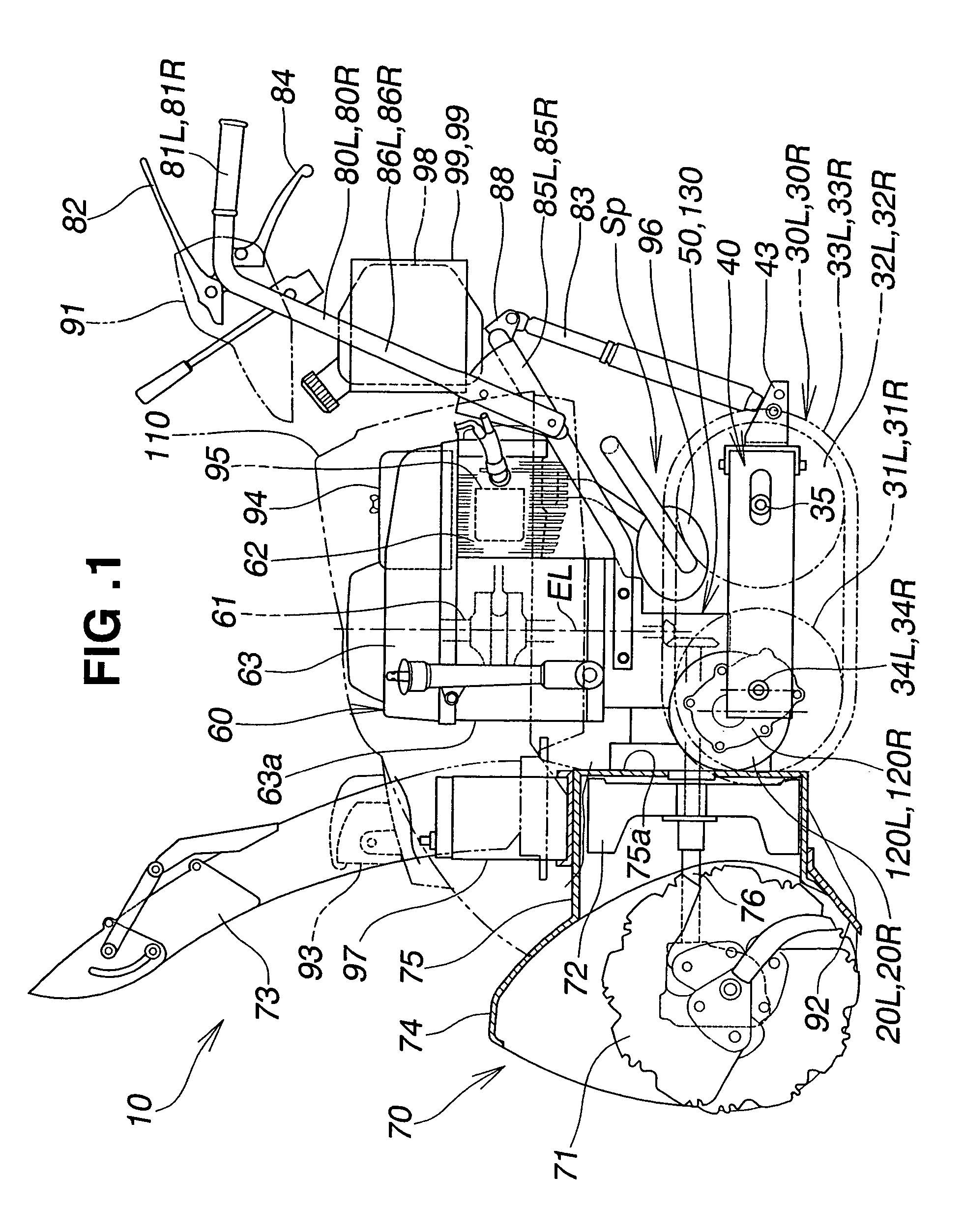
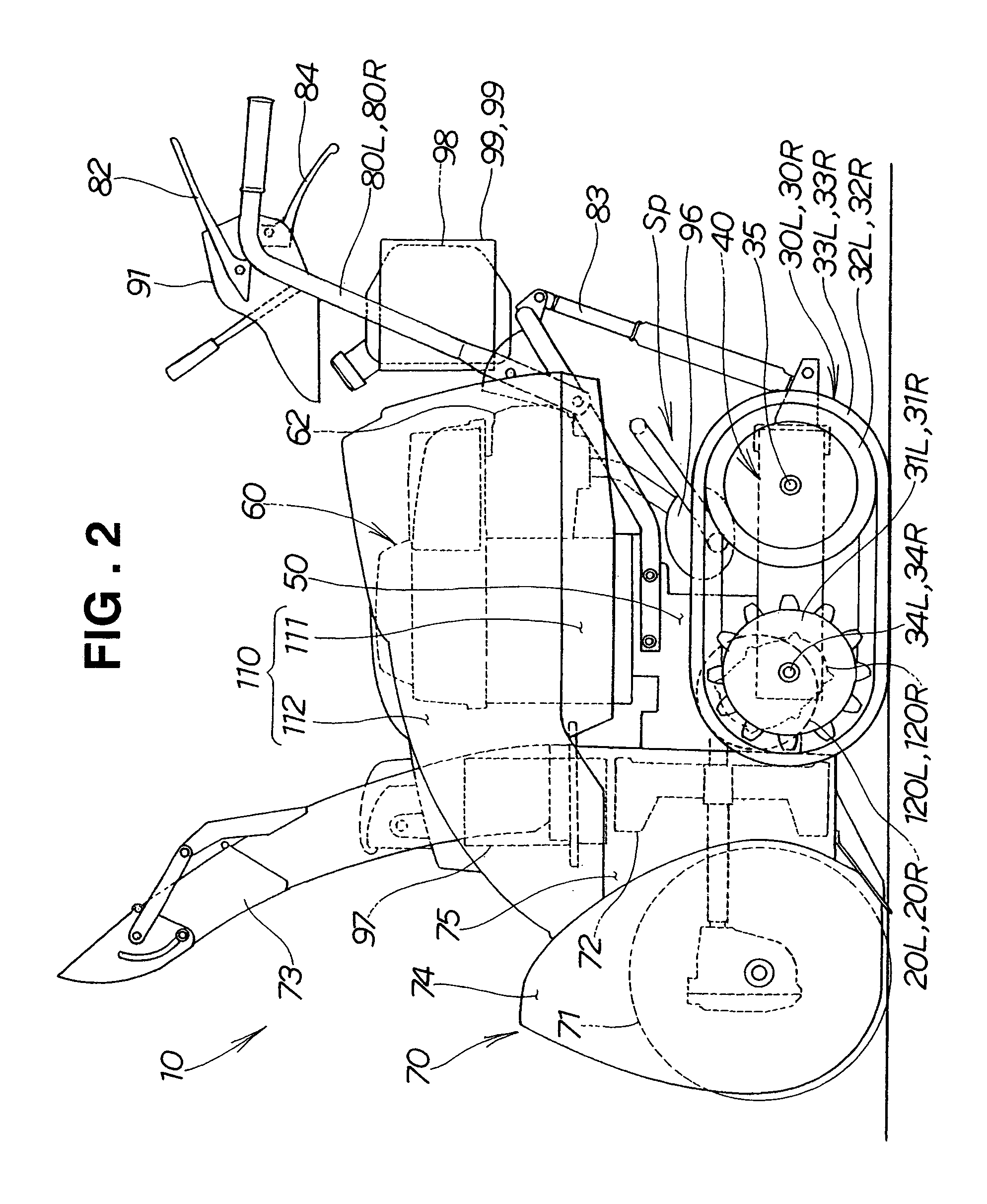
[0031]First, an exemplary snow removing machine equipped with electric motors according to the present invention will be described with reference to FIGS. 1 to 7.

[0032]A snow removing machine 10 shown in FIG. 1 includes a transmission case 50 doubling as a machine body, vertically swingably mounted to a crawler frame 40 having right and left travel units 30R, 30L (see FIG. 3).

[0033]Right and left electric motors 20R, 20L are mounted to the right and left sides of the transmission case 50. An engine 60 is mounted on top of the transmission case 50. A snow removing unit 70 is mounted to the front of the transmission case 50. Right and left operating handles 80R, 80L extend from upper portions of the transmission case 50 in a rearward and upward direction. An operating panel 91 is provided between the right and left operating handles 80R, 80L.

[0034]The snow removing machine 10 is a self-propelled, walk-behind working machine, which is led by an operator walking behind the operating pan...


PUM


Abstract

An electric motor including a stator with a plurality of coils wound around a ring-shaped iron core, and a rotor rotatably disposed inside the stator is provided. The rotor includes a rotor shaft and a yoke. The yoke is provided near its periphery with a plurality of plate-like permanent magnets arranged at equal pitches. Heat generated from the rotor is released through a plurality of air holes formed in the yoke between the rotor shaft and the permanent magnets.

Description

FIELD OF THE INVENTION[0001]The present invention relates to an improvement in an electric motor and, more particularly, to an inner-rotor brushless motor.BACKGROUND OF THE INVENTION[0002]Such a brushless motor is generally comprised of a stator with a plurality of coils wound around an iron core, a rotor rotatably disposed inside the stator, and a housing containing the stator and the rotor. The housing is provided with a plurality of air holes so that heat generated from the rotor and the stator is released through the air holes.[0003]A brushless motor having a cylindrical housing closed at its opposite ends with covers formed with air holes, and a rotor provided with a fan, is proposed in, e.g., Japanese Patent Laid-Open Publication No. HEI-1-110035. This brushless motor will be described in detail with reference to FIG. 15 hereof.[0004]A brushless motor 300 shown in FIG. 15 includes a stator 303 formed by winding coils 302 around an iron core 301, a rotor 307 provided inside the...

Claims


Application Information

Patent Timeline
Patent Type & Authority Patents(United States)
IPC IPC(8): H02K1/32H02K1/27H02K21/16
CPCH02K1/276H02K1/32B60L1/003B60L11/126B60L11/14B60L3/0061B60L2240/36B60L2200/40B60L50/16B60L50/62Y02T10/62Y02T10/64Y02T10/70Y02T10/7072
Inventor YAMAGISHI, YOSHIHIKOHIROSE, YOSHIHISA
Owner HONDA MOTOR CO LTD
Why Eureka
Try Eureka