Center tapped chip inductor
a center-tapped chip and inductor technology, applied in the direction of transformer/inductance details, inductances with magnetic cores, inductances with inductances, etc., can solve the problem that conventional chip inductors generally have a reduced quality factor (q)
- Summary
- Abstract
- Description
- Claims
- Application Information
AI Technical Summary
Problems solved by technology
Method used
Image

Examples
first embodiment
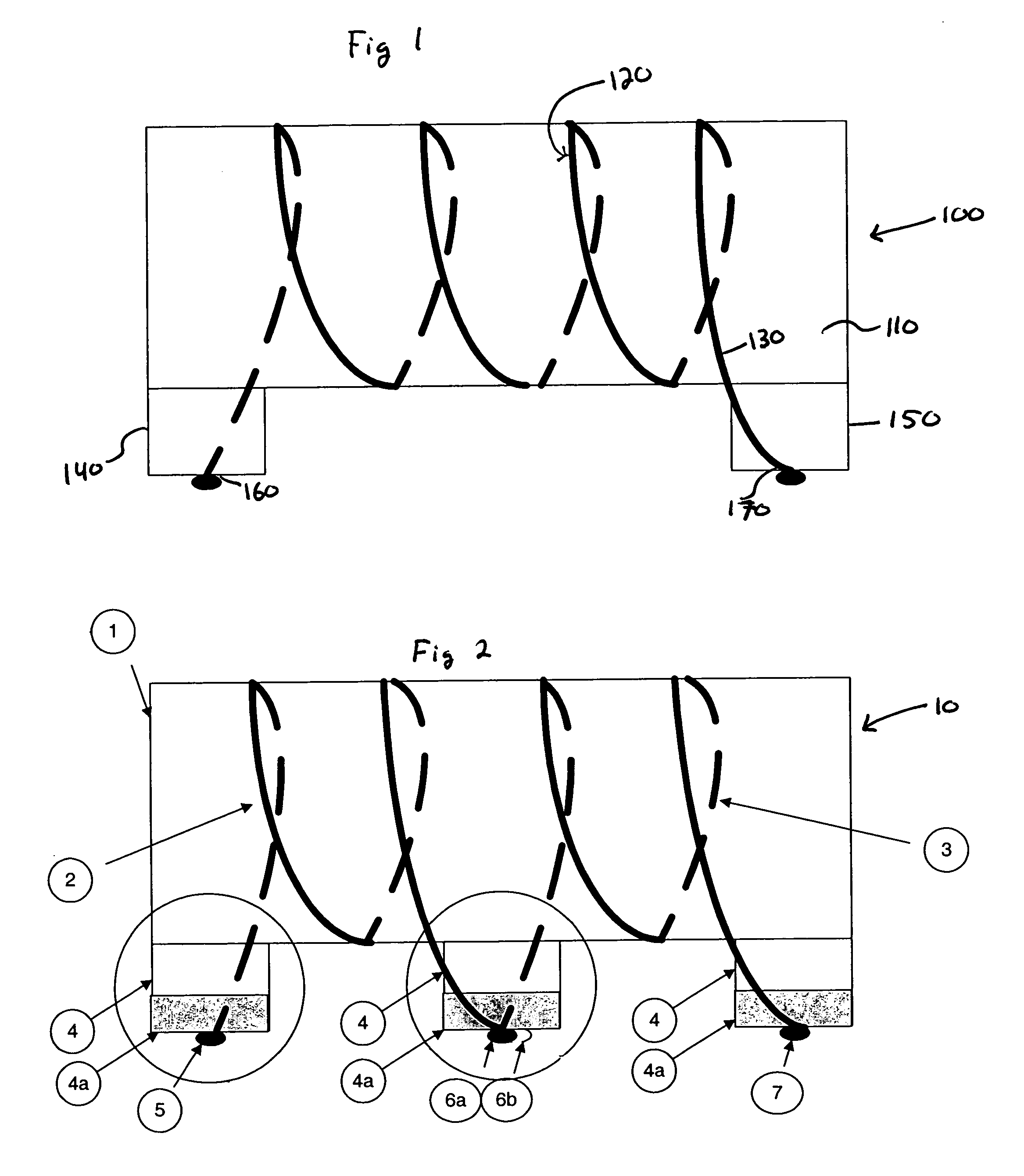
[0013]FIG. 2 is a schematic illustration of a center tap chip inductor 10. Chip inductor 10 includes a core 1 that may be a non-ferromagnetic (e.g., ceramic). A winding is wrapped about the core 1. The winding is formed, in this embodiment, from two separate wires 2, 3 having an appropriate diameter. Attached to the core 1 are a series of terminals or contacts 5, 6, and 7, each having a base 4 and a metal contact pad 4a to provide good electrical contact. There is a contact 5, 7 provided at each end of the core 1 as well as a center contact 6, medially disposed along the core 1.
[0014]The first wire 2 is wrapped about the core 1 and is coupled between the first contact 5 and the center contact 6. Similarly, the second wire 3 is wrapped about the core 1 and is coupled between the second contact 7 and the center contact 6. More specifically, as two wires 2, 3 are used in this embodiment, center contact 6 may include a separate contact point 6a, 6b for each such wire allowing for ease o...
second embodiment
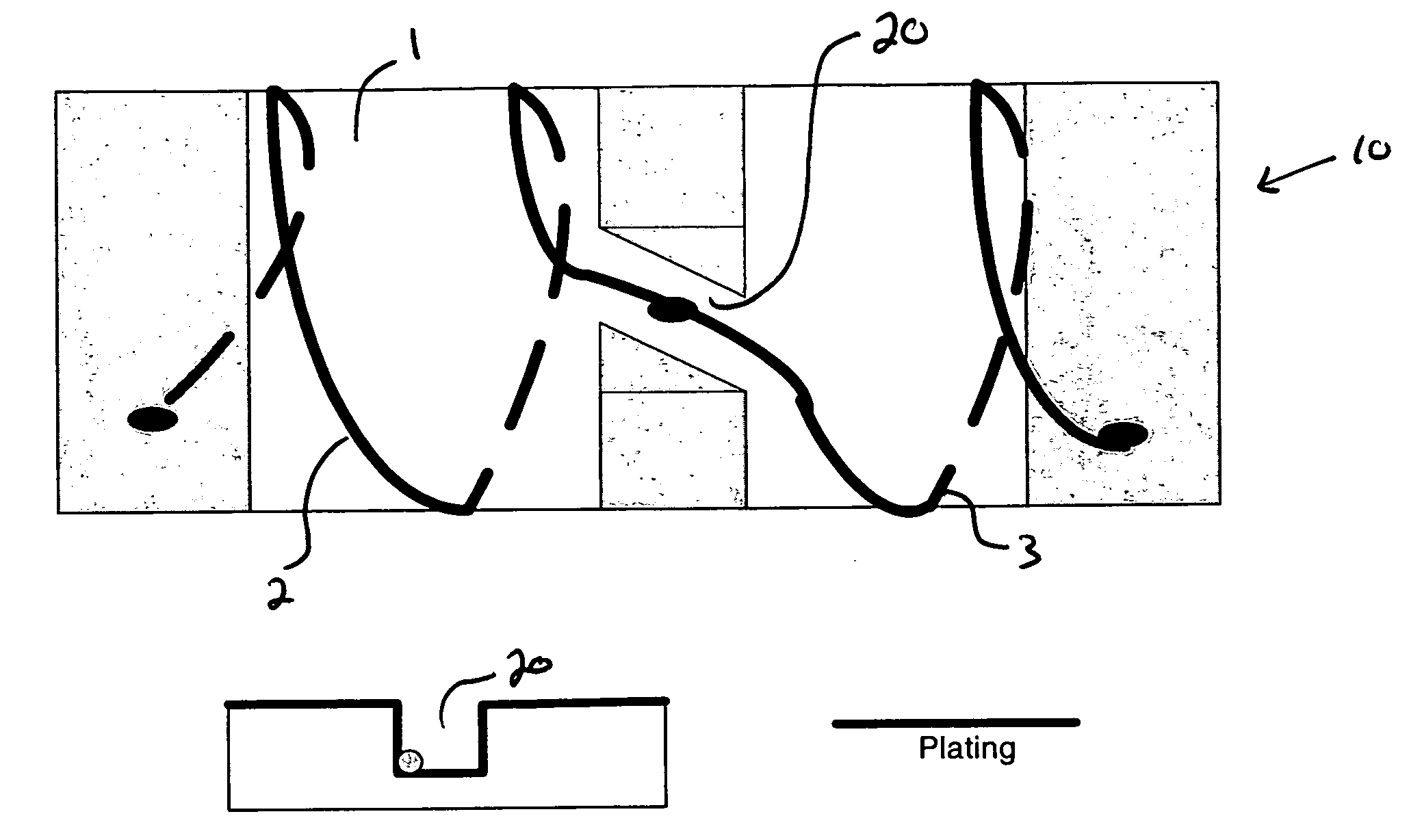
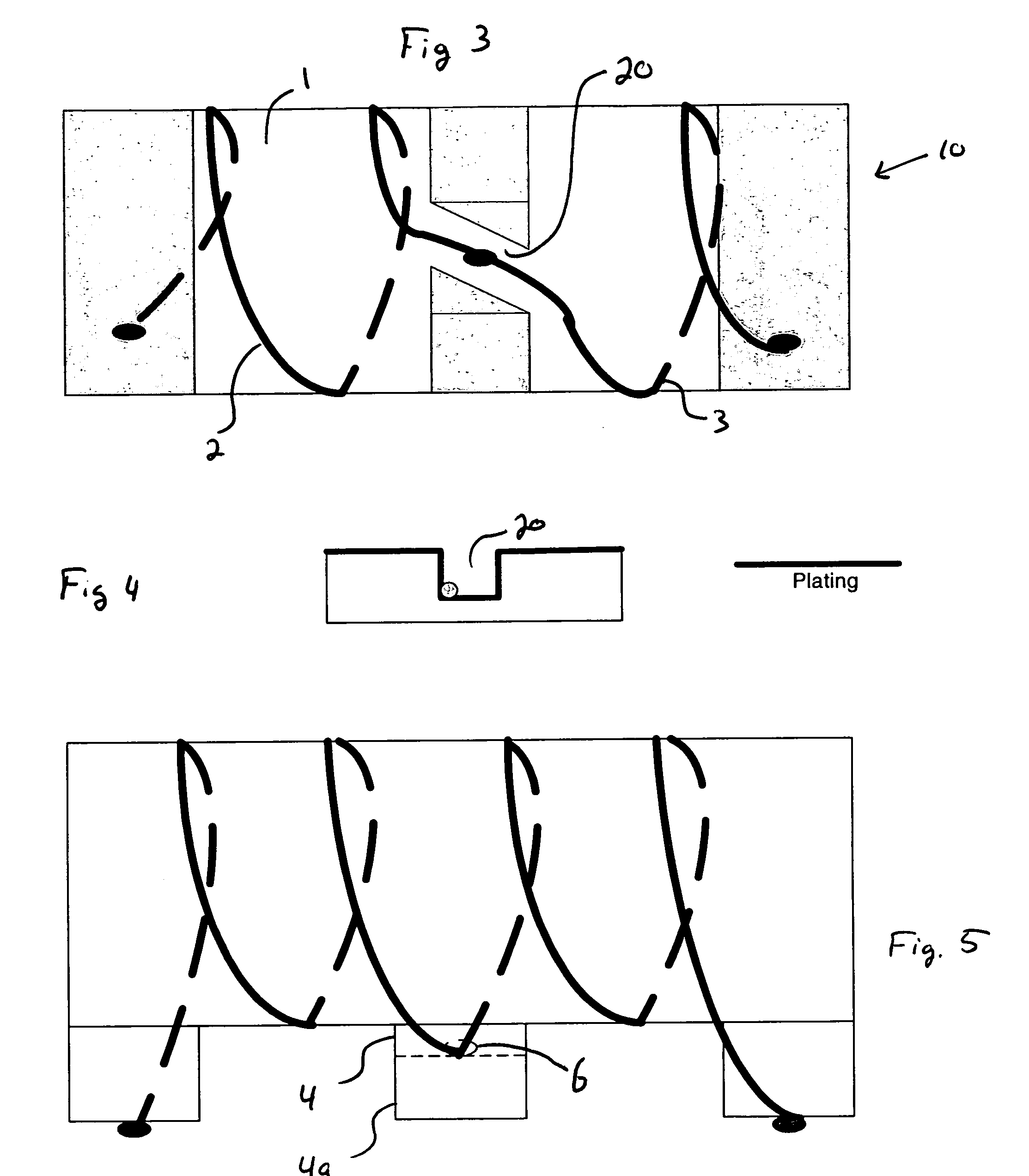
[0017]FIGS. 3–5 illustrate the center tap chip inductor 10. In this embodiment, a deformity, a passageway, a guide or equivalent structure is provided as represented by an exemplary channel 20 that is provided within the substrate or core 1. The channel 20 is provided to align the wire(s) 2, 3 with respect to the core 1 and the various terminals 5, 6, and 7. This embodiment also illustrates how the core 1 or portions thereof may be plated. For center tap 6, the contact between the wire 2, 3 and the terminal 4 is made to the top (as illustrated) of the contact pad 4a, rather than the bottom as previously illustrated.
[0018]Channel 20 may have any desired cross-sectional configuration, including, for example, rectilinear, circular, semi-circular / castellation, elliptical, angular, curvilinear, or otherwise. As illustrated, channel 20 is disposed at a non-perpendicular angle with respect to a main axis of the terminal 4. The channel 20 be positioned so as to be perpendicular to or to hav...
third embodiment
[0019]FIG. 6 illustrates the center tap chip inductor 10. In this embodiment, a through bore 30 is disposed through a portion of the core 1. The through bore 30 facilitates alignment of the wire(s) 2, 3 with the center terminal 6.
PUM
 Abstract
Description
Claims
Application Information
 - R&D
- Intellectual Property
- Life Sciences
- Materials
- Tech Scout
- Unparalleled Data Quality
- Higher Quality Content
- 60% Fewer Hallucinations
Browse by: Latest US Patents, China's latest patents, Technical Efficacy Thesaurus, Application Domain, Technology Topic, Popular Technical Reports.
© 2025 PatSnap. All rights reserved.Legal|Privacy policy|Modern Slavery Act Transparency Statement|Sitemap|About US| Contact US: help@patsnap.com