Zig-zag laser amplifier with polarization controlled reflectors

a laser amplifier and reflector technology, applied in the direction of laser details, active medium materials, active medium shape and construction, etc., can solve the problems of linear polarization no longer being effective, and the polarization properties of the amplified output can degrade significantly

Inactive Publication Date: 2006-10-17
NORTHROP GRUMMAN SYST CORP
View PDF14 Cites 9 Cited by
  • Summary
  • Abstract
  • Description
  • Claims
  • Application Information

AI Technical Summary

Benefits of technology

[0005]The present invention resides in an optical amplifier comprising an elongated slab of a solid state lasing material having a predetermined cross-section defining opposing end faces, a plurality of lateral faces, a longitudinal axis defined between the opposing end faces generally parallel to the lateral faces; means for enabling pumped light to be directed along an axis generally parallel to the longitudinal axis; and one or more sources of pump beams. An input optical beam is repeatedly reflected between two opposed lateral faces as it progresses through and is amplified in the elongated slab. In accordance with the invention, the slab includes a complex evanescent coating disposed on the two opposed lateral faces, to reduce depolarization arising from birefringence accumulated upon propagation of a beam through the slab.
[0006]More specifically, the complex evanescent coating is selected to provide a selected phase retardance at each total internal reflection of the input optical beam as it zig-zags through the slab, the selected phase retardance resulting in minimization of the total accumulated depolarization. For example, the complex evanescent coating may be selected to provide a phase retardance of approximately zero at total internal reflection for the input optical beam. Ideally, the complex coating is selected to provide approximately the same selected phase retardance over a range of angles of incidence of the input optical beam with respect to the opposed lateral faces.
[0008]It will be appreciated from the foregoing that the present invention represents a significant advance in solid state laser amplifiers. Specifically, the use of a complex coating on opposed lateral faces of a zig-zag slab laser provides for polarization control and eliminates a serious drawback of optical amplifiers of this type when used at higher powers. Other aspects and advantages of the invention will become apparent from the following more detailed description, taken in conjunction with the accompanying drawings.

Problems solved by technology

As this zig-zag slab architecture has been extended to higher powers, it has been found that the polarization properties of the amplified output can degrade significantly, such that linear polarization can no longer be maintained effectively.

Method used


Image

  • Zig-zag laser amplifier with polarization controlled reflectors
  • Zig-zag laser amplifier with polarization controlled reflectors
  • Zig-zag laser amplifier with polarization controlled reflectors

Examples


Embodiment Construction

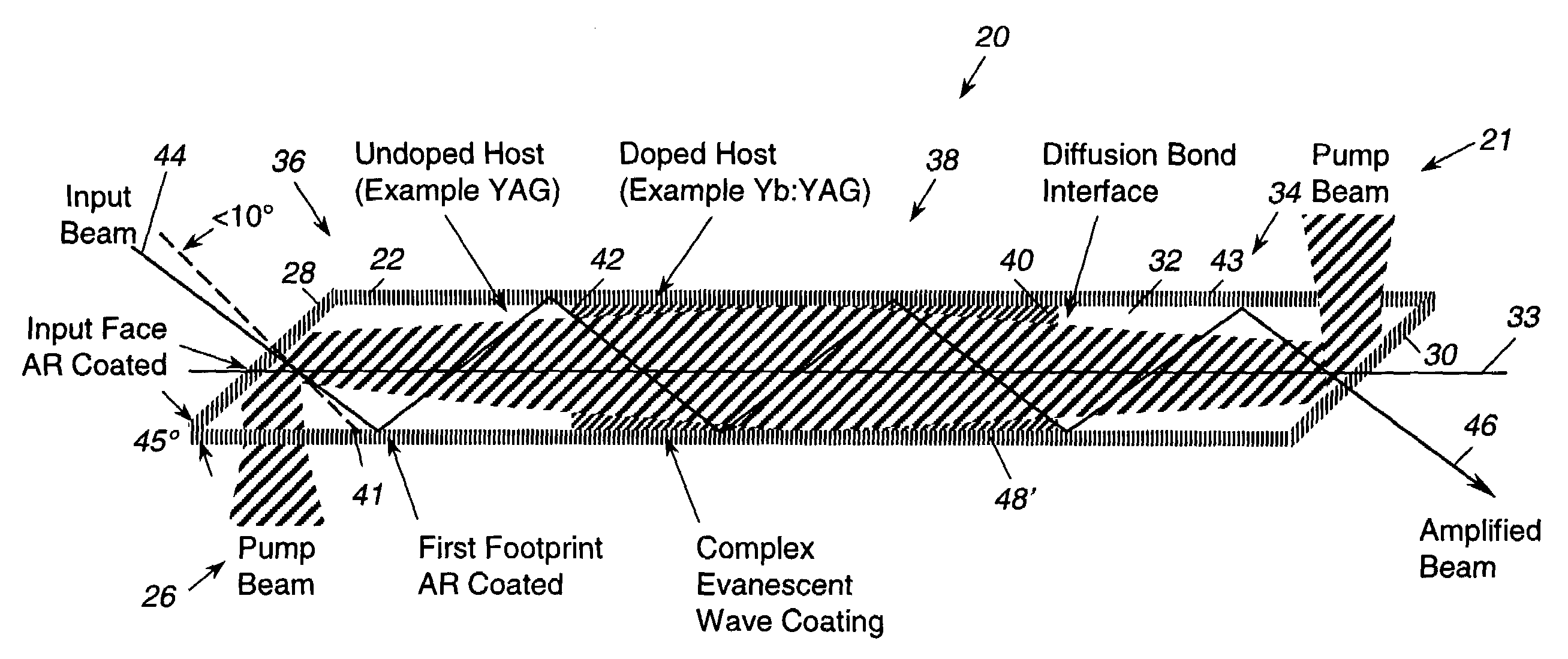
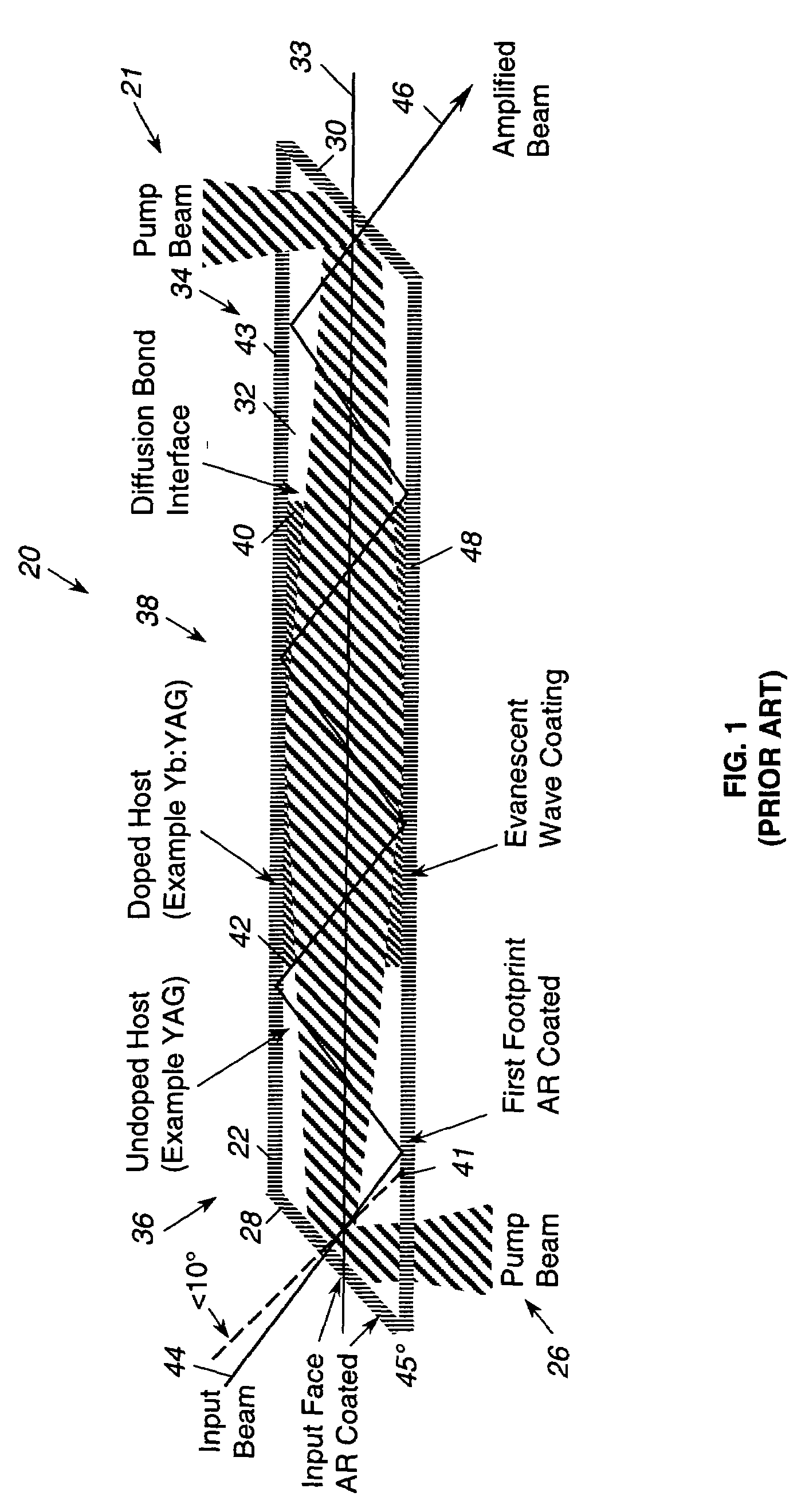
[0015]As shown in the drawings for purposes of illustration, the present invention is concerned with techniques for controlling polarization in a zig-zag slab laser amplifier. FIG. 1 is a cross-sectional view of a zig-zag slab laser amplifier of the prior art, as illustrated in U.S. Pat. No. 6,094,297, referred to in this document as the Injeyan '297 patent, which is hereby incorporated by reference into this document.

[0016]In the Injeyan '297 device, and in the present invention, an optical amplifier, generally identified by reference numeral 20, utilizes end pumping. With such a configuration, pumped light is generally co-aligned with amplified light along a longitudinal axis of a slab 22, resulting in a relatively long absorption length and providing relatively higher overall efficiencies. This configuration is particularly suitable for optical amplifiers that utilize solid state lasing material with relatively low absorption coefficients, such as those materials using ytterbium ...


PUM


Abstract

A solid state zig-zag slab laser amplifier in which depolarization occurring at total internal reflection from opposed lateral faces of the amplifier slab is controlled by selecting a complex evanescent coating that provides a selected phase retardance that results in minimization of depolarization. Without use of the complex coating, small changes in incidence angles can result in phase retardance changes large enough to increase depolarization significantly, especially when the amplifier is operated at higher powers. Appropriate selection of the complex evanescent coating allows a desired phase retardance angle to be maintained relatively constant over a small range of angles of incidence, at a given wavelength, and therefore permits minimization of depolarization and birefringence effects.

Description

BACKGROUND OF THE INVENTION[0001]This invention relates generally to laser amplifiers and, more particularly, to end-pumped zig-zag solid state lasers. A zig-zag solid state laser includes an elongated slab of rare earth doped lasing material, such as yttrium-aluminum-garnet (YAG). An input beam generated by a master oscillator is launched into one end facet of the slab, at an angle selected to result in multiple internal reflections from the internal faces of the slab. A pump beam is also input at one end of the slab and amplification of the input beam takes place as the input beam is reflected back and forth along the slab. The doped region of the slab in which amplification takes place is cooled by external means.[0002]The laser structure briefly described above is disclosed in detail in U.S. Pat. No. 6,094,297, referred to in this document as the Injeyan '297 patent, issued to Hagop Injeyan et al. and assigned to the same assignee as the present invention.[0003]Although the ampl...

Claims


Application Information

Patent Timeline
Patent Type & Authority Patents(United States)
IPC IPC(8): H01S3/10H01S3/00H01S3/06H01S3/08H01S3/13H01S3/042H01S3/0941H01S3/16H01S3/23
CPCH01S3/0606H01S3/2333H01S3/005H01S3/042H01S3/0612H01S3/0625H01S3/08095H01S3/0941H01S3/1301H01S3/1618H01S3/1643
Inventor ROTHENBERG, JOSHUA E.LONG, JR., WILLIAM H.GOODNO, GREGORY D.EPP, PAUL T.
Owner NORTHROP GRUMMAN SYST CORP
Why Eureka
Try Eureka