
Wind power installation and method and apparatus for use in association therewith

a technology for wind power installation and wind power, which is applied in the direction of sports equipment, liquid/fluent solid measurement, indication/recording movement, etc., to achieve the effect of reliable estimation of important parts and reliable detection of loading

Inactive Publication Date: 2006-10-24
WOBBEN ALOYS
View PDF10 Cites 14 Cited by
  • Summary
  • Abstract
  • Description
  • Claims
  • Application Information

AI Technical Summary

Benefits of technology

[0005]Each loading makes a contribution to material fatigue. It is therefore easy to understand that, at locations with a large number of high loadings, fatigue progresses more quickly than at locations with few and low loadings.
[0008]An object of one aspect of the invention is to provide an apparatus and a method which permits reliable detection of the loading on the wind power installation and a reliable estimate of important parts of the wind power installation.
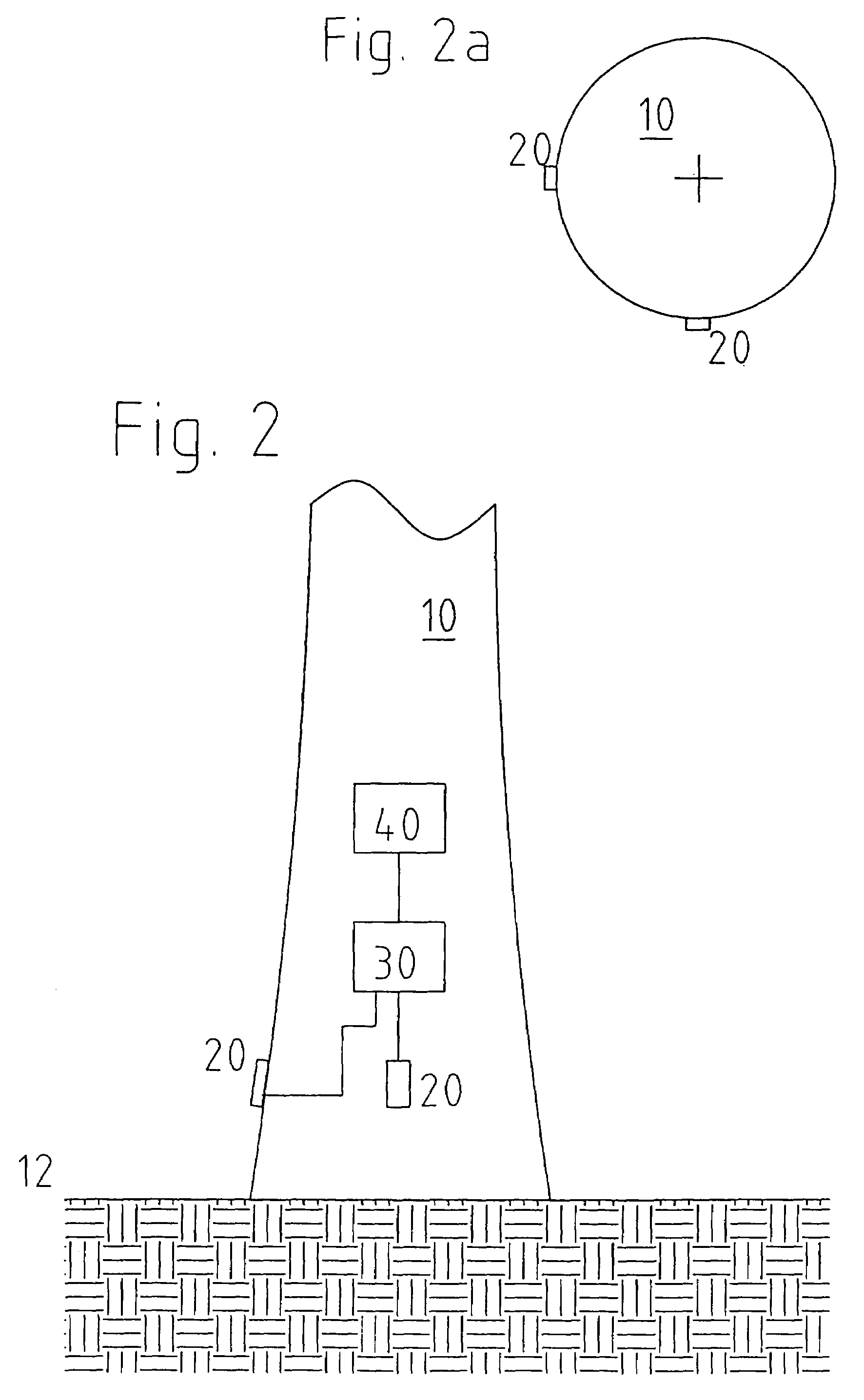
[0011]As, in a simplification, the wind power installation can be viewed as a bar which is gripped at one end, it is possible to detect the sum of all loads acting on the wind power installation, at the base of the pylon. Arranging at least one sensor in the region of the base of the pylon therefore permits reliable detection of the loading on the wind power installation. At the same time it is possible to reach the sensor without aids and without involving a high degree of expenditure and complication.
[0013]The measurement values detected by the resistance strain gauge are particularly preferably converted into analog or digital electrical signals which are representative of the measurement values. Those signals can be transmitted and subjected to further processing in a simple manner.
[0015]It will be appreciated that the result of the cumulation can also in turn be compared to a predeterminable limit value. In that way it is possible to consider the loading on the installation in relation to the design loads and thus to implement an estimate of the mechanical service age of the installation.
[0018]The measured loading data can also be subjected to further processing in a control apparatus of the wind power installation in such a way that, when an overload occurs, the control apparatus implements measures which result in a reduction in the loading. Such a reduction in loading can be effected for example by adjustment of the rotor blades (out of the wind) or also by a reduction in the speed of rotation of the rotor of the wind power installation. In addition the entire rotor of the wind power installation could be rotated out of the wind through a given angle, to reduce the loading.

Problems solved by technology

With the previous arrangements, the mechanical service age of a pylon can still not be adequately detected, so that ultimately it is only possible to arrive at vague estimates about the service life of a pylon and thus one of the most important parts of the wind power installation.

Method used


Image

  • Wind power installation and method and apparatus for use in association therewith
  • Wind power installation and method and apparatus for use in association therewith
  • Wind power installation and method and apparatus for use in association therewith

Examples


Embodiment Construction

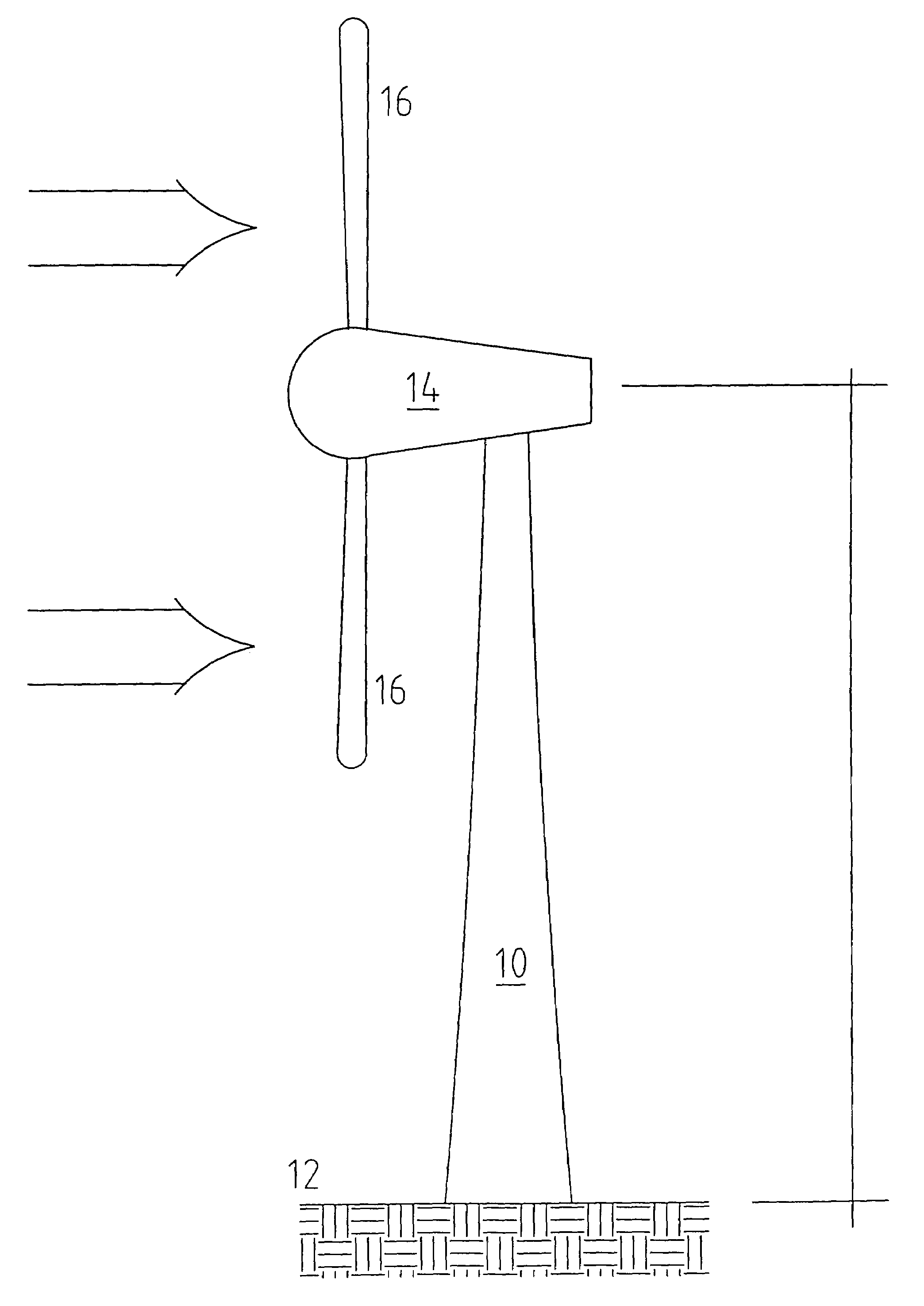
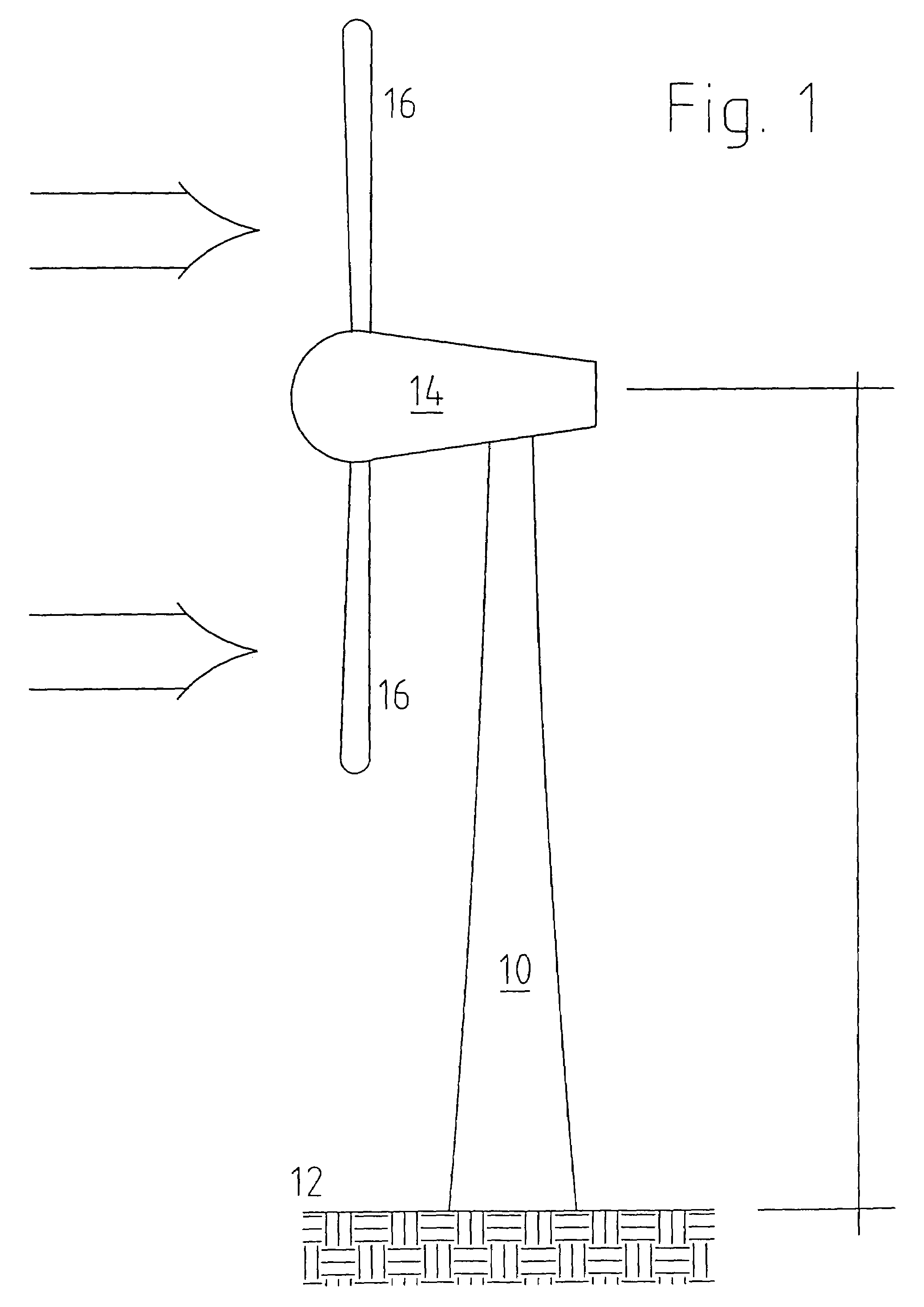
[0024]FIG. 1 shows a pylon 10 of a wind power installation, which is connected to a foundation 12. Arranged at the head of the pylon 10 is a pod 14 which has a rotor which rotor blades 16. In this Figure the arrow denotes the direction of the wind.

[0025]The wind rotates on the one hand the rotor and therewith the subsequently mechanically coupled part of the wind power installation in order to generate electrical energy. At the same time however on the one hand the pylon 10 is subjected to the effect of the pressure of the wind and on the other hand the pod 14 with the rotor is deflected in the direction of the wind. As a result, a bending moment occurs at the pylon 10 which is gripped at one end, over the lever arm of the length of the pylon, at the foundation 12.

[0026]The effect of the force acting on the head of the pylon produces a force pattern over the entire length of the pylon so that the alternating loads or oscillations cause a corresponding material fatigue effect.

[0027]F...


PUM


Abstract

The present invention concerns an apparatus for monitoring a wind power installation, with at least one sensor for detecting measurement values, and also a method of monitoring a wind power installation, in which: (i) a measurement value is detected with at least one sensor, (ii) the measurement value is converted into a signal representative of the measurement value, and (iii) the signal is stored and / or processed in accordance with a predetermined method. In one aspect, in order to provide an apparatus and a method which permit reliable detection of the loading on the pylon of the wind power installation, there is provided at least one sensor for detecting the loading on the pylon, the sensor being arranged in the region of the base of the pylon. In addition, the instantaneous loading on the wind power installation is ascertained from the signal representative of the measurement value ascertained by the sensor.

Description

RELATED INFORMATION[0001]The present invention concerns a wind power installation having a monitoring apparatus, with at least one sensor for detecting measurement values, and also a method of monitoring a wind power installation, in which a) a measurement value is detected with at least one sensor, b) said measurement value is converted into a signal representative of the measurement value, and c) the signal is stored and / or processed in accordance with a predetermined method.[0002]Such apparatuses and methods are known in the state of the art. The journal ‘Erneuerbare Energien’ [‘Renewable Energies’], issue July 2000, page 38, which appeared at SunMedia Verlags- und Kongressgesellschaft für Erneuerbare Energien mbH Hannover, in an article entitled ‘Knackt der Rotor den Turm’ [‘The rotor roughs up the pylon’], mentions oscillation monitoring by means of acceleration measurement.[0003]Issue No May 2000 of that journal, in paragraph 2 on page 37 thereof, describes that the oscillatio...

Claims


Application Information

Patent Timeline
Patent Type & Authority Patents(United States)
IPC IPC(8): G01P5/00F03D11/04F03D7/00F03D7/02F03D7/04F03D11/00
CPCF03D7/00F03D7/0224F03D11/0091F05B2240/912F05B2240/913F05B2270/1095F05B2270/331F05B2270/332F05B2270/808Y02E10/722Y02E10/723Y02E10/728F03D17/00Y02E10/72
Inventor WOBBEN, ALOYS
Owner WOBBEN ALOYS
Learn More