

Installation structure of intake manifold
a technology of installation structure and intake manifold, which is applied in the direction of air intakes for fuel, machines/engines, combustion-air/fuel-air treatment, etc., can solve the problems of defective sealing, defective sealing, and restricted layout around the cylinder head, so as to ensure the mounting strength facilitate the mounting operation of the intake manifold
- Summary
- Abstract
- Description
- Claims
- Application Information
AI Technical Summary
Benefits of technology
Problems solved by technology
Method used
Image

Examples
Embodiment Construction
[0047]Hereinafter, embodiments of the present invention will be described with reference to the drawings.
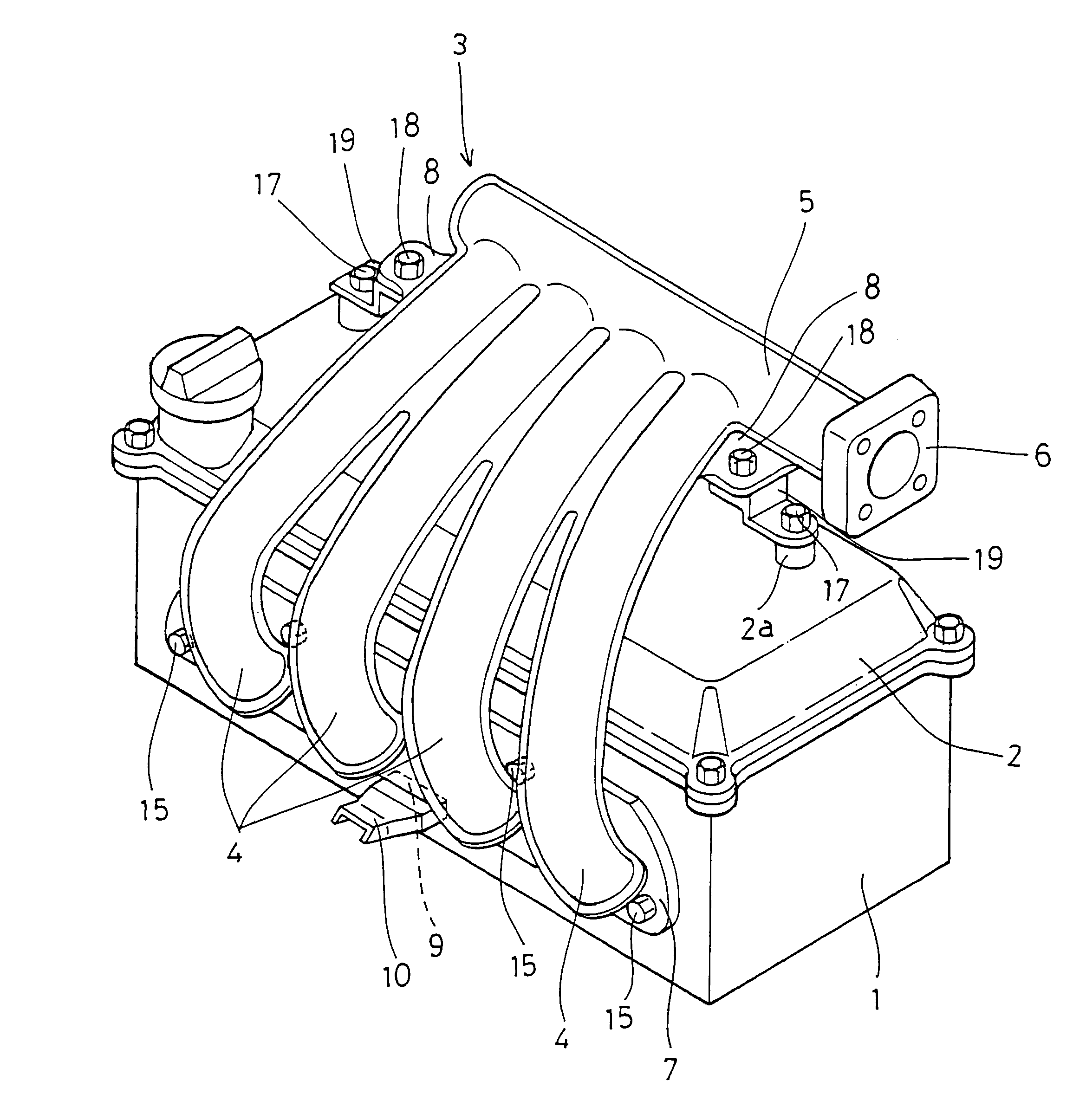
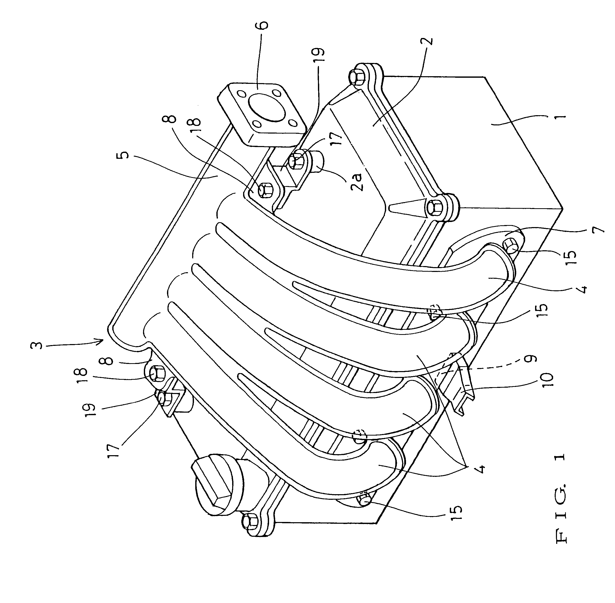
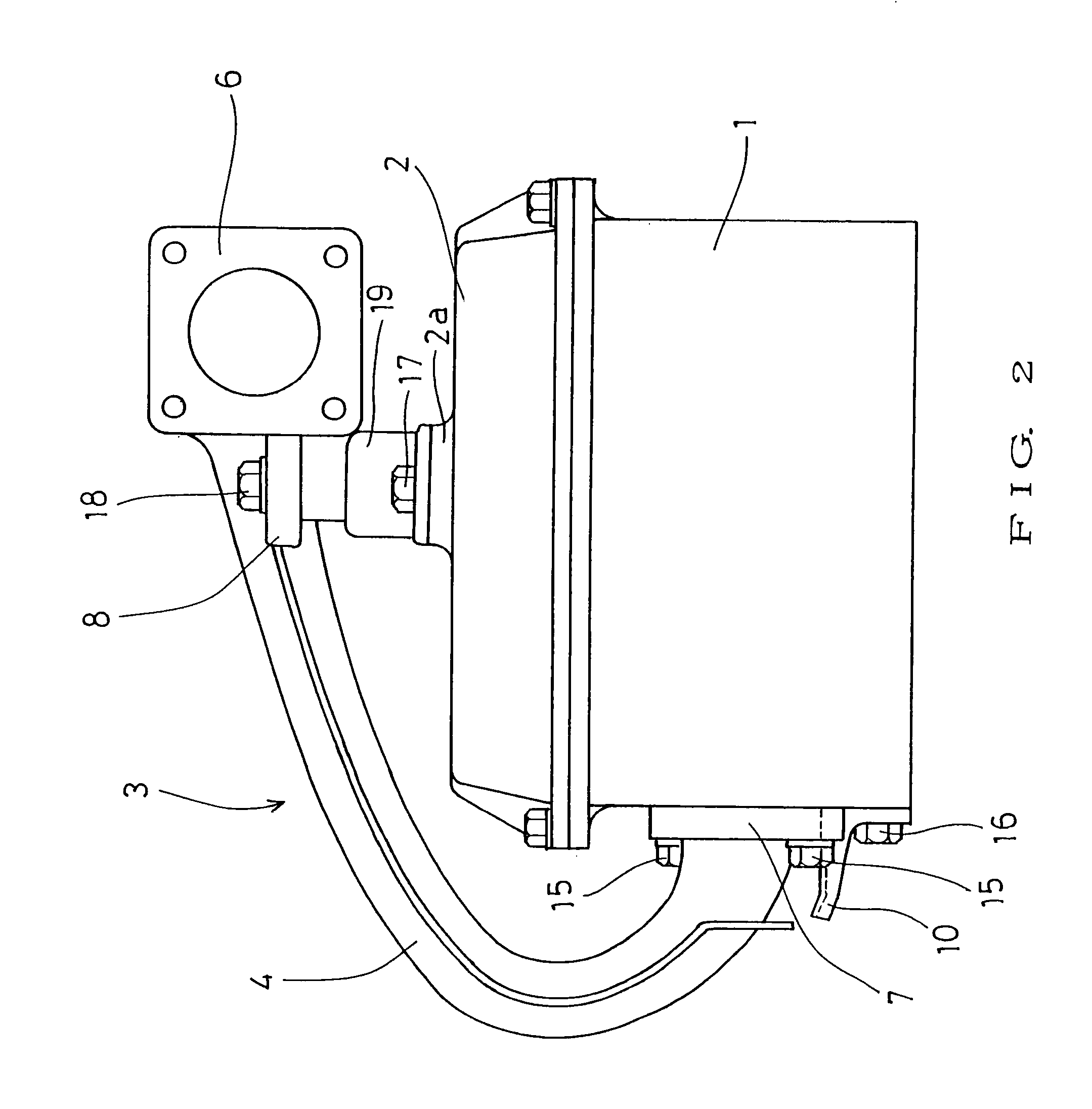
[0048]FIG. 1 is a perspective view of a mounting structure of an intake manifold mounted on a cylinder head. FIG. 2 is a side view, and FIG. 3 is a plan view of the same.
[0049]In the drawings, the top surface of a cylinder head 1 is covered with a rocker cover 2, and an intake manifold 3 is mounted on the lateral side of the cylinder head 1 via a flange 7.
[0050]The intake manifold 3 includes four branch tubes 4 having upstream-side ends to which the flange 7 is mounted. On the upstream-side ends of the branch tubes 4, there is provided a plenum chamber portion 5 having the right end to which a throttle chamber mounting flange 6 is mounted.
[0051]In this embodiment of the intake manifold 3, the right and left outer branch tubes 4, 4 on the side of the plenum chamber 5 are integrally formed with respective flat portions 8, 8 projecting laterally.
[0052]The flat portions 8 are provide...
PUM
| Property | Measurement | Unit |
|---|---|---|
| taper angle | aaaaa | aaaaa |
| mounting structure | aaaaa | aaaaa |
| size | aaaaa | aaaaa |
Abstract
Description
Claims
Application Information