Means and method for filling bag-on-valve aerosol barrier packs

a technology of aerosol barrier pack and valve, which is applied in the directions of packaging goods, liquid handling, transportation and packaging, etc., can solve the problems of high disadvantage, and achieve the effect of simple and efficien

Inactive Publication Date: 2006-10-24
PRECISION VALVE CORP
View PDF26 Cites 35 Cited by
  • Summary
  • Abstract
  • Description
  • Claims
  • Application Information

AI Technical Summary

Benefits of technology

[0007]A first aspect of the present invention allows the above-described propellant pressure filling to be used in a bag-on-valve system when the bag is already connected to the valve housing and the valve is fixed to the container. This is accomplished by providing an annular interior surface on the valve housing, for example a frusto-conical surface, and an annular exterior surface on the valve stem, for example a frusto-conical surface, the two said surfaces sealingly contacting each other only when the downward engagement pressure of the propellant filling head pushes the valve stem down the full distance to make such contact upon propellant filling. This downward pressure of the filling head will exceed the normal actuating pressure of the valve user in a downward or sideward direction on the stem to cause valve actuation and dispensing. Thus, the said respective frusto-conical surfaces of the stem and housing will not contact and seal against each other during normal valve actuation, since such contact and sealing during actuation would prevent product exiting the product bag into the valve housing and out the valve. The said respective frusto-conical surfaces of the stem and housing, upon sealing against each other during propellant filling, block propellant during filling entering into the product bag. Stem and housing surface profiles other than frusto-conical may be utilized as long as they effectively seal against each other to prevent propellant entering into the product bag.
[0008]In a second aspect of the present invention, the product bag in the can, sealingly connected to the valve housing, may be filled with product after (or before) the above-described propellant filling. The product filling is carried out through the dispensing conduit of the valve stem, with the valve stem being depressed a distance considerably less than during propellant filling but a sufficient amount to unseal the stem lateral orifices from the valve gasket. Product, for example a gel, flows down the center conduit of the valve stem, through the stem lateral orifices, into the valve housing interior, and down into the bag connected to the valve housing. The valve stem is held at a predetermined position of depression by a combination of a stem configuration and a novel insert adaptor configuration in the product filling head. More particularly, an annular indentation in the surface of the valve stem is utilized for engagement with spring loaded radial slides in the insert of the product filling head to maintain the position of the valve stem during filling. (Such stem indentations have been previously utilized, but for the unrelated purpose of securing actuator buttons). Without such a locking interengagement, the stem position can fluctuate under the pressure of product entering the valve stem. This fluctuation can either cause the stem to rise during product filling to partially or completely close the stem lateral orifices to prevent product filling, or may depress the stem so far as to seal the stem against the housing by the afore-described annular frusto-conical surfaces to prevent product filling down into the bag.

Problems solved by technology

The presence of such a connected product bag creates a serious impediment to such propellant filing in that the propellant passing around the stem also can pass between the bent valve gasket and the adjacent valve stem into the interior of the valve housing between the housing inner wall and the stem outer wall.
This of course is highly disadvantageous in a bag-on-valve barrier pack wherein the product and propellant are to be maintained separate from one another.

Method used


Image

  • Means and method for filling bag-on-valve aerosol barrier packs
  • Means and method for filling bag-on-valve aerosol barrier packs
  • Means and method for filling bag-on-valve aerosol barrier packs

Examples


Embodiment Construction

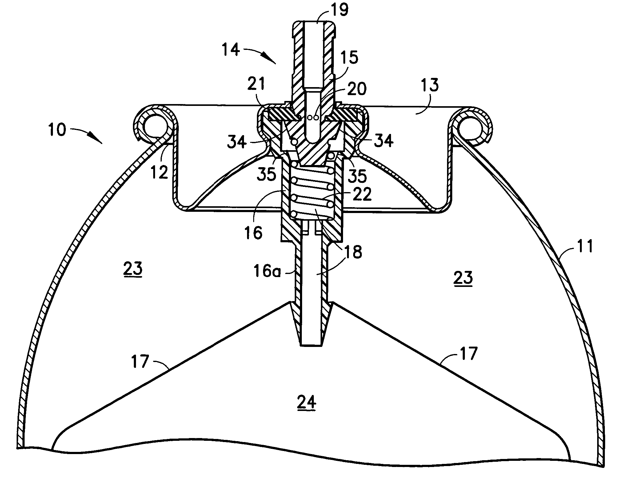
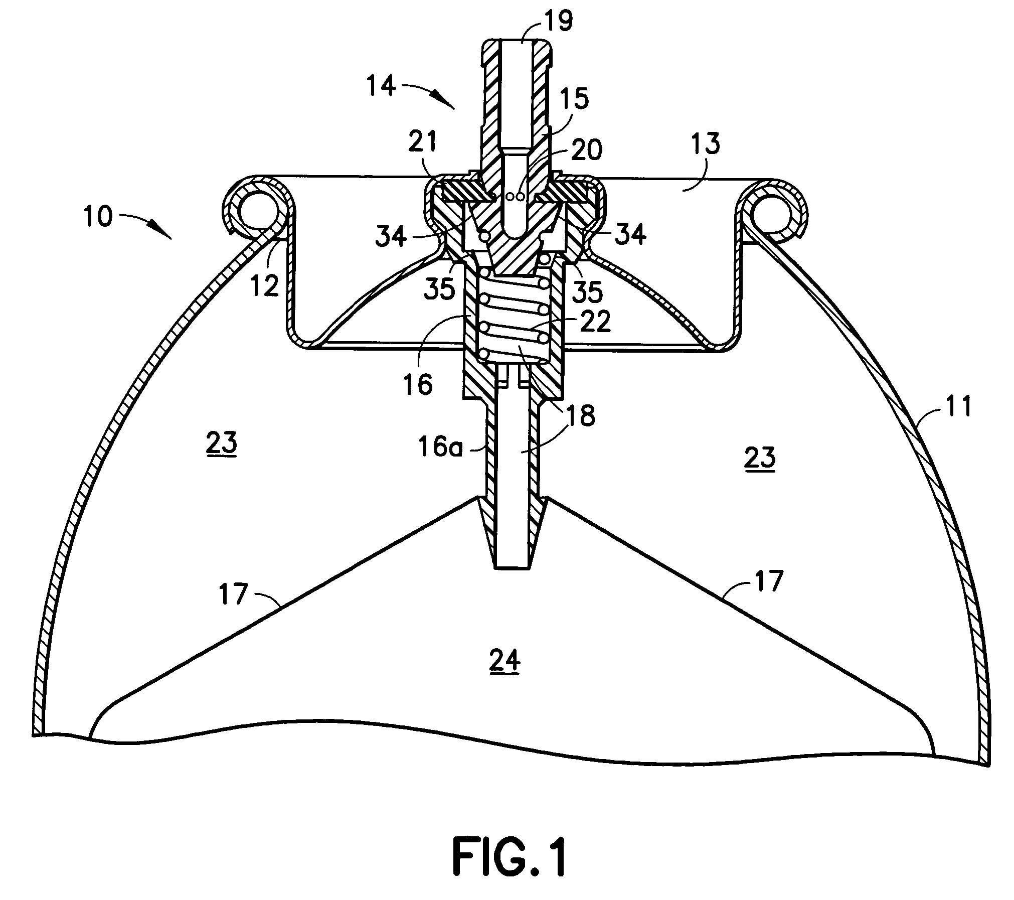
[0018]Referring to FIG. 1, aerosol valve system 10 includes a conventional closed container or can 11 (only the top portion of which is shown) with a top circular opening 12 within which is mounted aerosol mounting cup 13. Centrally disposed within mounting cup 13 is aerosol valve 14 comprised of valve stem 15 and valve housing 16. Valve housing 16 at the extension 16a of its lower end has a flexible product bag 17 attached thereto in a sealingly connected manner. Flexible bag 17 may be comprised of polyethylene and / or other materials (including in laminated form) and is of well known structure. Bag 17 will contain the product to be dispensed from the aerosol container, and is a closed structure throughout except at the top of the bag where it is open only into the interior 18 of the valve housing. The bag 17 is welded all about its top opening to the outside of the lower extension 16a of the valve housing. The bag 17 alternatively may be welded to a wedge or other fixture at the en...


PUM

PropertyMeasurementUnit
angleaaaaaaaaaa
flexibleaaaaaaaaaa
pressureaaaaaaaaaa

Abstract

A bag-on-valve aerosol valve system in a container. Propellant is pressure filled around the valve stem, outwardly over the stem gasket and down into the container space outside the bag. Product is filled through the valve stem into the bag. The valve stem has an exterior intermediate frusto-conical annular surface and the valve housing has an interior frusto-conical annular surface, with both surfaces engaging in annular sealing contact to block propellant access to the bag when the valve stem is deeply depressed to a first predetermined position for propellant pressure filling. A stem exterior surface indent interacts with radially-biased spring-loaded slides to lock the stem in a second less depressed predetermined position for product filling through the stem down into the bag. The propellant and product may be pressure filled in either order using essentially conventional pressure filing equipment, after the valve is mounted on the container and the bag is mounted on the valve.

Description

FIELD OF THE INVENTION[0001]The present invention relates to the filling of propellant and product into aerosol containers. More specifically, the invention relates to the filling of such containers of the bag-on-valve barrier pack type wherein a bag within the container is intended to hold the product to be dispensed and the remainder of the container is intended to hold the propellant.BACKGROUND OF THE INVENTION[0002]Aerosol containers of the barrier pack type include the well-known piston-in-can, and bag-in-can, embodiments. In one form of the latter, to which the present invention is directed, a flexible bag within the can may have its open end sealingly connected to the valve housing of the aerosol valve. Such embodiments are referred to as bag-on-valve systems. The product to be dispensed from the aerosol container commonly is filled into the flexible bag within the container and a liquified propellant or compressed gas is filled into the aerosol container outside of the bag b...

Claims


Application Information

Patent Timeline
Patent Type & Authority Patents(United States)
IPC IPC(8): B65B1/04B65B31/00B65D83/14
CPCB65B31/003B65D83/425B65D83/62B65B1/04
Inventor PERICARD, LOUIS
Owner PRECISION VALVE CORP
Why Eureka
Try Eureka