Multi-purpose equipment

a multi-purpose, equipment technology, applied in the direction of manufacturing tools, lighting and heating apparatus, instruments, etc., can solve the problems of insufficient flexibility of non-tool accessories, deficiency of wrist-worn devices of the prior art, and inability to integrate non-tool accessories with tools. , to achieve the effect of convenient and inexpensive modification

Inactive Publication Date: 2006-10-24
TAYLOR BRANDS
View PDF78 Cites 59 Cited by
  • Summary
  • Abstract
  • Description
  • Claims
  • Application Information

AI Technical Summary

Benefits of technology

[0017]The housing of the present invention is specifically designed for easy and inexpensive modification at the manufacturing level. The primary structural components of the housing comprise a spacer sandwiched between front and rear plates. The multi-function module is retained by a module-receiving cavity attached to the front plate. The spacer defines the shape and thickness of the accessory compartment and the tool pod. At the manufacturing level, changing the thickness or configuration of the accessory compartment and / or the tool pod is a simple matter of using a differently sized spacer.

Problems solved by technology

Hand-held tools or devices that can perform multiple functions are not new.
While quite suitable for the functions that they are designed to perform, these types of tools do not provide sufficient flexibility to integrate non-tool accessories.
The wrist-worn devices of the prior art are deficient in that they do not provide sufficient flexibility to offer electronic functions in combination with other useful devices, such as tools or accessories.
In addition, operation of the wrist-worn electronic devices of the prior art is complicated, requiring reliance on a printed manual to access and / or use many of their features.
McIntosh is deficient in that its design cannot accommodate a wide variety of combinations and configurations of devices, it is not particularly attractive, and has no electronic device capabilities.

Method used


Image

  • Multi-purpose equipment
  • Multi-purpose equipment
  • Multi-purpose equipment

Examples


compass embodiment

Electronic Compass Embodiment

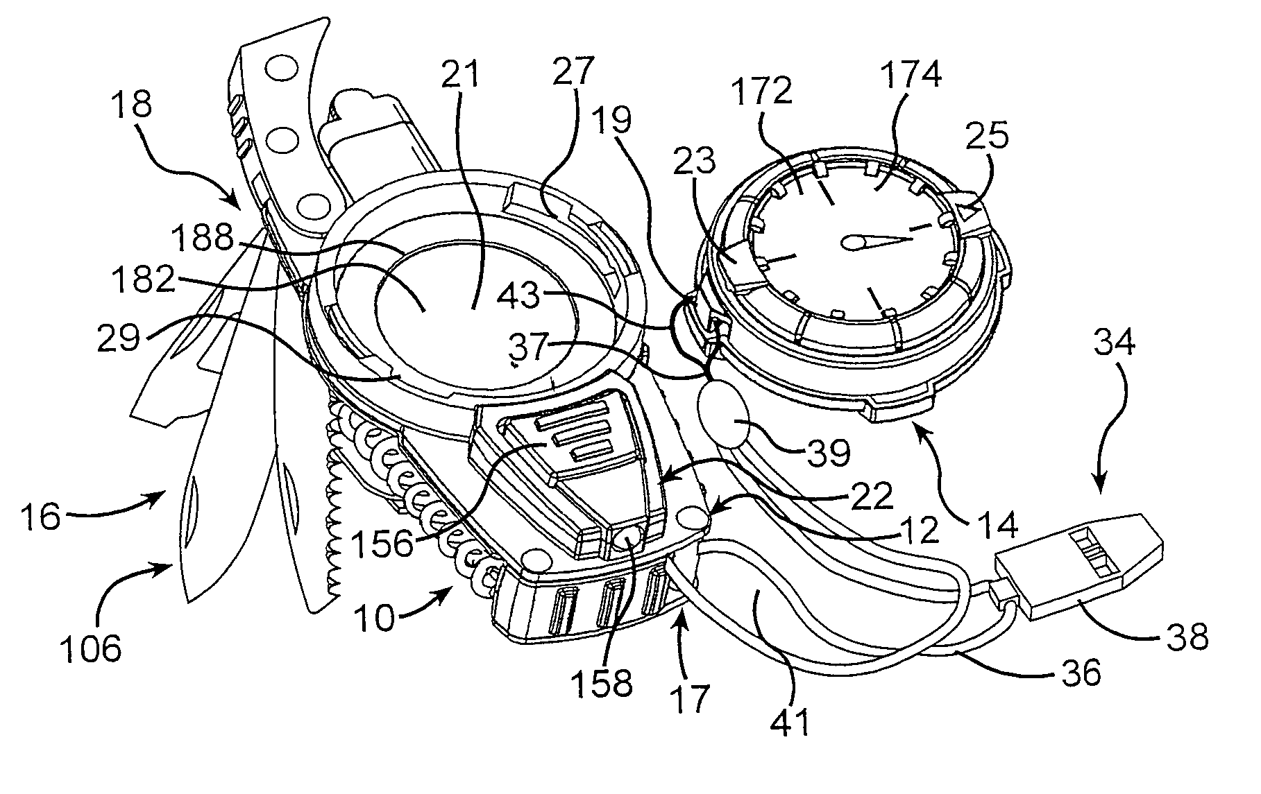
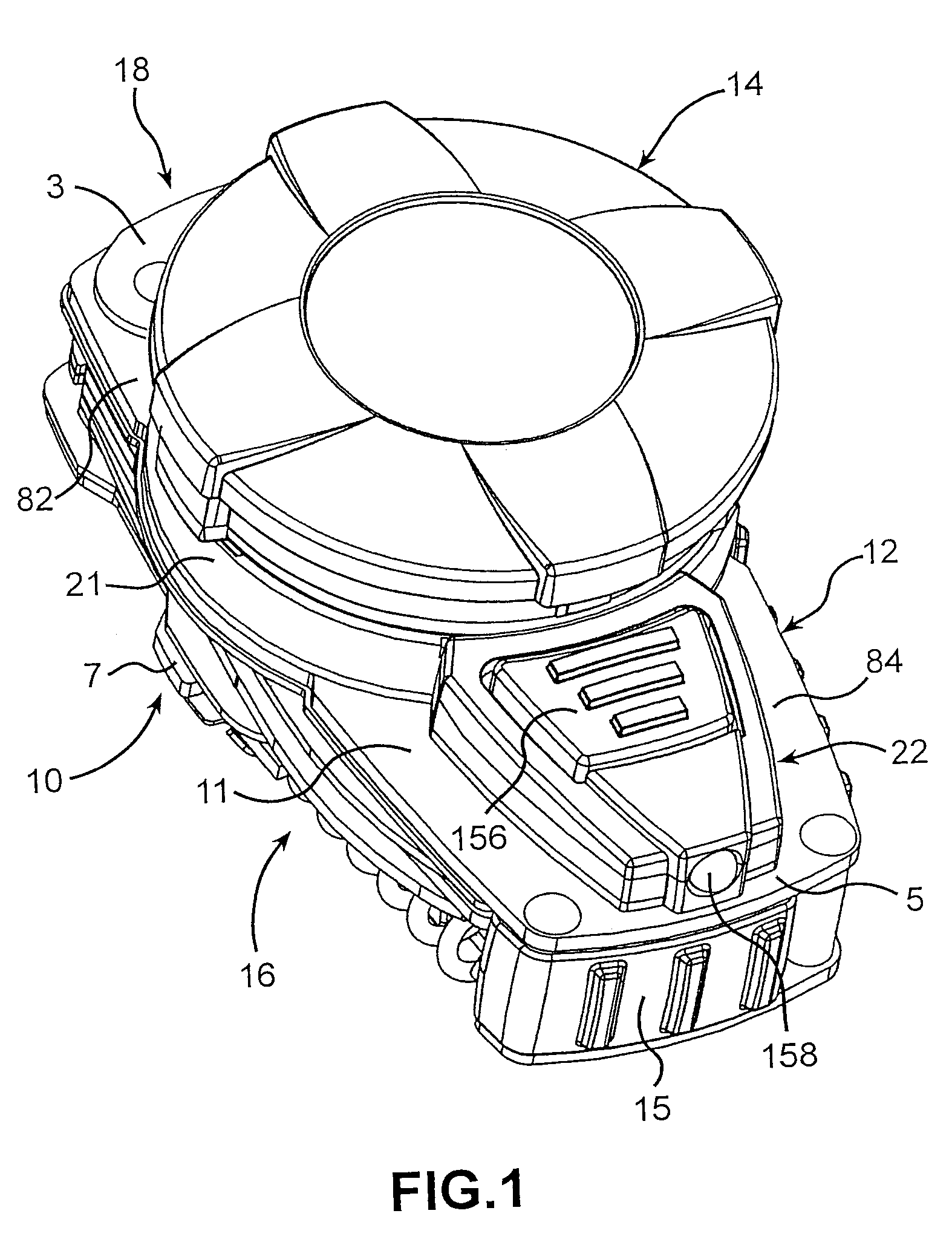
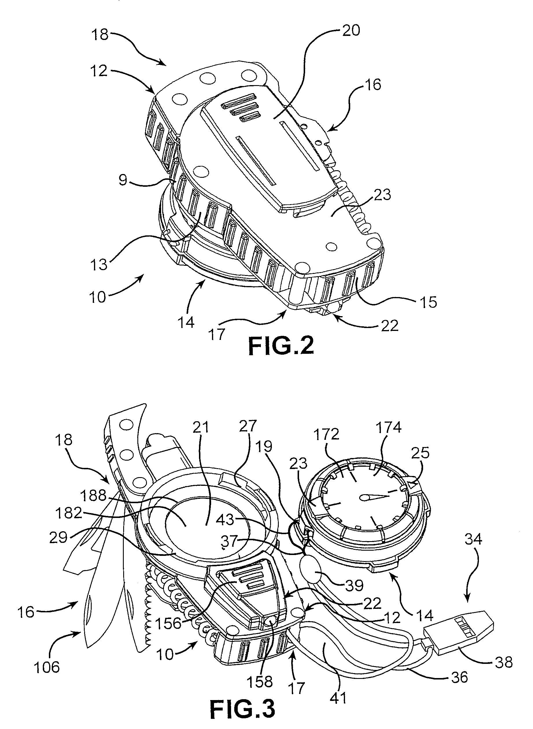
[0079]Referring now to FIGS. 7 & 7A, equipment 110 is shown with an alternative multi-function module 214. The structure of housing 112 is substantially the same, if not identical, to the housing 12 of the mechanical compass embodiment described in detail above. Multi-function module 214 comprises an electronic compass 215 that includes the capability of displaying a variety of information, including time, date, stopwatch, temperature, direction, absolute and relative barometric pressure, and altitude above sea level. Module 214 may optionally include a signal mirror 217 incorporated into housing 112 which is formed of a reflective material, such as polished steel.

[0080]Compass 215 is operated by four buttons 310, 312, 314, and 316 (see FIG. 14—only buttons 312&314 are visible in FIGS. 7 & 7A). As will be described in greater detail herein, the functions and operation of electronic compass 215 represents a marked improvement over similar devices in the p...


PUM


Abstract

Multi-purpose equipment 10 is disclosed having a modular housing 12, a multi-function module 14 for containing electronic or mechanical devices, a tool pod 16 having multiple tools 106 pivotally attached thereto, an accessory compartment 18 for removably containing, for example, a disposable lighter 32. Module 14 is preferably removable and is adapted contain an electronic or mechanical device, such as a mechanical compass 172, an electronic compass 215, or other electronic devices. Tool pod 16 includes a plurality of pivotally attached tools 106. A lanyard 34 may also be provided to tether module 14 to housing 12.

Description

CROSS-REFERENCE TO RELATED APPLICATIONS[0001]This application claims priority from U.S. provisional application Ser. No. 60 / 102,172, filed May 26, 2000, and U.S. provisional application Ser. No. 60 / 258,095, filed Dec. 26, 2000.TECHNICAL FIELD[0002]This invention relates to modular multi-purpose equipment comprising a combination of tools, electronic and / or mechanical devices, and other accessories.BACKGROUND ART[0003]Hand-held tools or devices that can perform multiple functions are not new.[0004]One category of such devices is multi-tools, i.e., pliers in combination with multiple folding tools, such as knife blades, screwdrivers, bottle cap and can openers, and the like. The TOUGH™ tool multi-tool pliers by Imperial Schrade Corp. (disclosed, e.g., in U.S. Pat. No. 5,791,002) and the PST™ multi-tool by Leatherman Tool Group, Inc. (disclosed in U.S. Pat. No. 4,744,272) are representative of the state of the multi-tool art. While quite suitable for the functions that they are designe...

Claims


Application Information

Patent Timeline
Patent Type & Authority Patents(United States)
IPC IPC(8): F21V33/00B25F1/04B26B11/00F23Q2/32G01C17/00
CPCB25F1/04B26B11/001B26B11/008F23Q2/32G01C17/00
Inventor GARDINER, WALTER A.HUFNAGEL, JOSEPH A.QUINN, JAMES O.LYNCH, PETER F.OSIECKI, SCOTT W.ENGLERT, ROBERT S.HAYDUKE, NICHOLAS P.
Owner TAYLOR BRANDS
Why Eureka
Try Eureka