
Heterodyne frequency modulated signal demodulator and method of operating the same

a demodulator and heterodyne technology, applied in the field of demodulators for heterodyne frequency modulated signals, can solve the problems of undesirable number of detectors, complex system of heterodyne interferometers, and drawbacks of interferometers, and achieve the effect of improving the signal-to-noise ratio

Inactive Publication Date: 2006-10-24
THE BOEING CO
View PDF9 Cites 4 Cited by
  • Summary
  • Abstract
  • Description
  • Claims
  • Application Information

AI Technical Summary

Benefits of technology

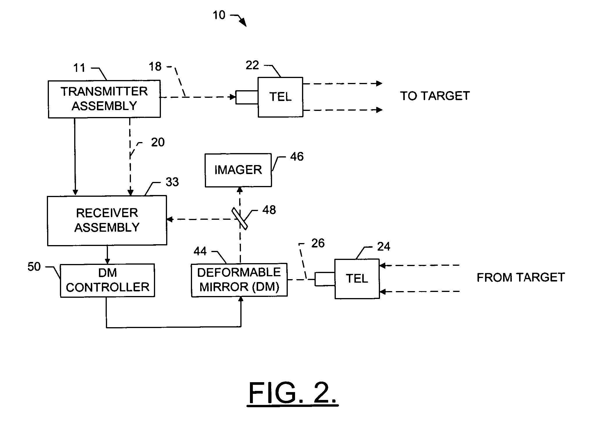
[0007]In light of the foregoing background, embodiments of the present invention provide an improved heterodyne interferometer, and an associated adaptive optics system. Embodiments of the present invention also provide an improved method of measuring movement of a target, variations in a beam propagation medium (e.g., as such may be due to atmospheric turbulence) or the like, where variations in the beam propagation medium may be represented by optical path differences between the system and the target. Embodiments of the present invention also provide an improved method controlling an adaptive optics system. Advantageously, the heterodyne interferometer of embodiments of the present invention operates by producing a frequency change using an electrical frequency modulated (FM) signal, where the frequency change is proportional to the phase change in the target leg based upon interference between an optical local oscillator beam and an optical reflected beam from the target. In this regard, the heterodyne interferometer of embodiments of the present invention need not determine an absolute phase measurement of any resulting fringes, such as by utilizing techniques including fringe counting, zero-crossing phase detecting, and the like. Also, by producing the frequency change using the electrical FM signal, the heterodyne interferometer of embodiments of the present invention can be utilized to control an adaptive optics system without requiring a separate wavefront sensor, reconstructor or the like to determine the aberrated wavefront required to correct for optical path differences to the target, which may be represented by the phase measurement of the resulting fringes. Further, by interfering an optical local oscillator beam and an optical reflected beam from the target, the power of the reflected beam can be amplified above the shot noise, thus improving the signal-to-noise ratio.

Problems solved by technology

Whereas conventional heterodyne interferometers are adequate in measuring displacement due to movement of a target and / or atmospheric turbulence, such interferometers have drawbacks.
Among the drawbacks, conventional heterodyne interferometers are often complex systems that can be expensive to produce.
Further, many conventional interferometers require an undesirable number of detectors to receive the beam from the measurement arm of the interferometer due to required signal-to-noise ratios.

Method used


Image

  • Heterodyne frequency modulated signal demodulator and method of operating the same
  • Heterodyne frequency modulated signal demodulator and method of operating the same
  • Heterodyne frequency modulated signal demodulator and method of operating the same

Examples


Embodiment Construction

[0019]The present invention now will be described more fully hereinafter with reference to the accompanying drawings, in which preferred embodiments of the invention are shown. This invention may, however, be embodied in many different forms and should not be construed as limited to the embodiments set forth herein; rather, these embodiments are provided so that this disclosure will be thorough and complete, and will fully convey the scope of the invention to those skilled in the art. Like numbers refer to like elements throughout.

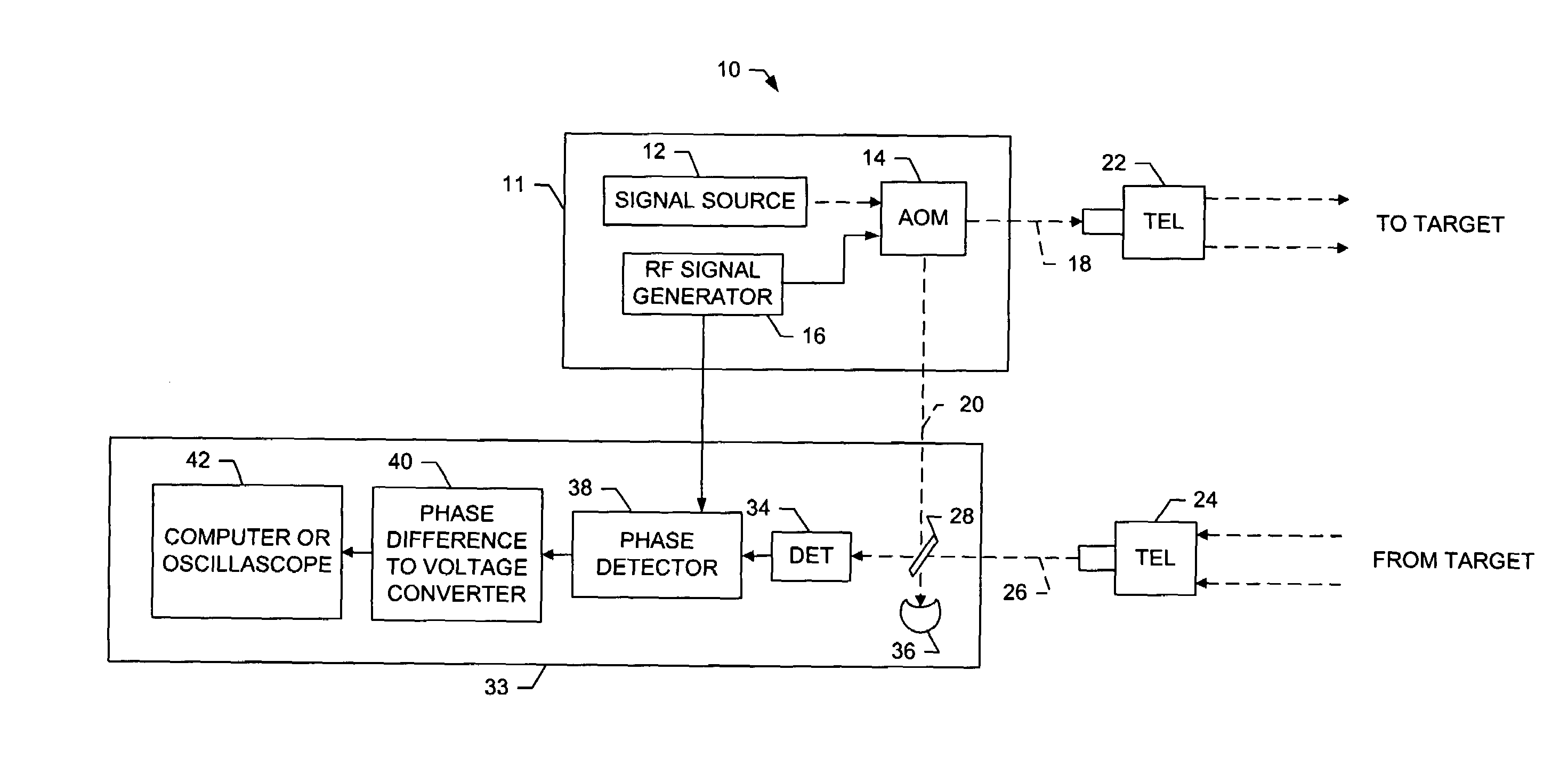
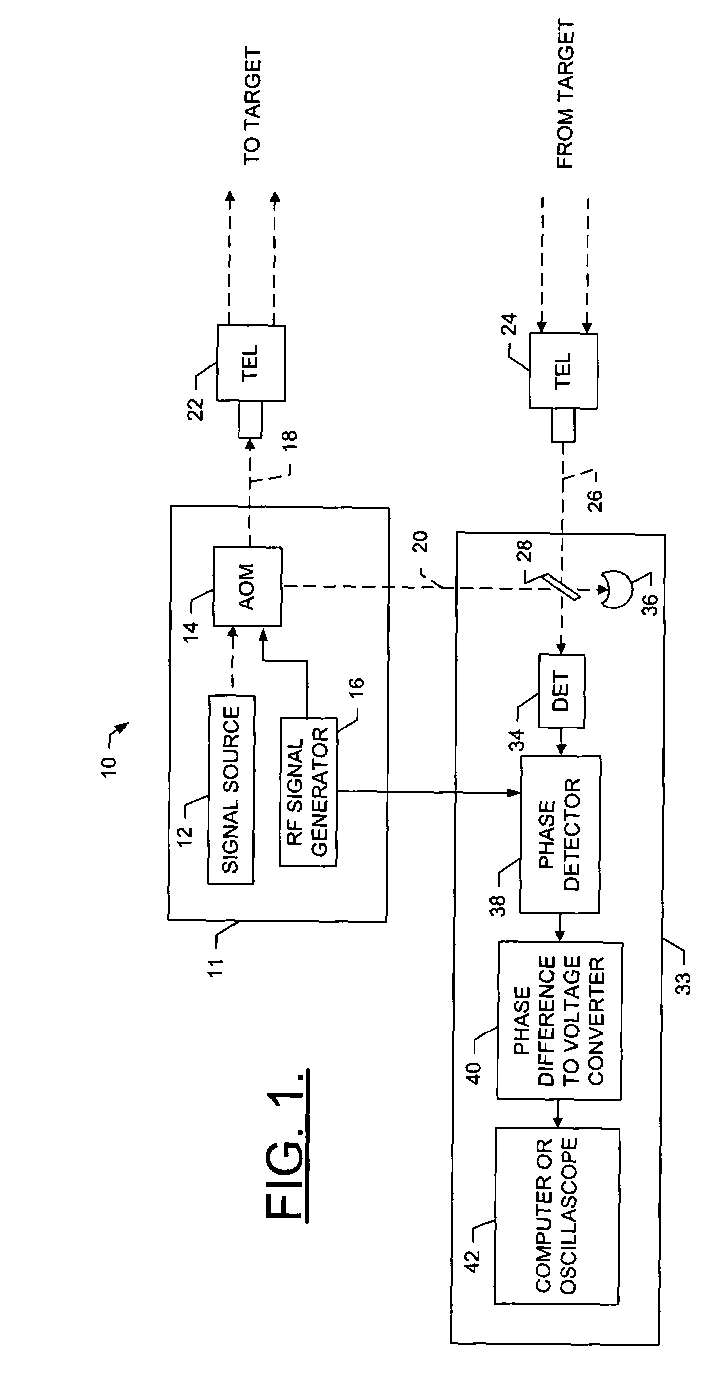
[0020]Referring to FIGS. 1 and 2, a heterodyne interferometer system 10 according to one embodiment of the present invention is shown where the system has a bi-static construction. The system according to various embodiments will be shown and described as including a number of optical and electrical components operating in a manner as described herein to obtain a measurement of the movement, or vibration, of a target and / or variances in a beam propagation ...


PUM


Abstract

A heterodyne interferometer, adaptive optics system, method of measuring movement of a target and / or variations in a beam propagation medium, and method of controlling an adaptive optics system are provided. The heterodyne interferometer includes an acoustic-optical modulator that can superimpose a RF signal on a source signal, and output a zero order beam and a higher order beam. One of the beams comprises a target beam and the other beam comprises a local oscillator beam. A telescope can receive the target beam, and direct the target beam through the beam propagation medium to the target. A beam splitter can receive the local oscillator beam and the reflected beam from the target, and coherently combine the local oscillator beam and the reflected beam to produce a fringe pattern. A detector can receive the fringe pattern and generate an electrical beat signal, which can be demodulated based upon the RF signal.

Description

FIELD OF THE INVENTION[0001]The present invention relates generally to methods and apparatus for determining the displacement or location of a target and, more particularly, to a demodulator for heterodyne frequency modulated signals and methods of operating the same.BACKGROUND OF THE INVENTION[0002]Heterodyne interferometers are utilized in a variety of commercial and noncommercial applications, such as to measure displacement, force, pressure or other physical quantities that create a measurable displacement in a respective transducer. For example, heterodyne interferometers may be utilized in an adaptive optics system to measure movement of a target and / or variations in a medium of beam propagation, such as may be due to atmospheric turbulence. By measuring movement and / or variations in the beam propagation medium, then, the adaptive optics system can correct for such movement and / or variations to accurately image the target.[0003]Heterodyne interferometers include a stable optic...

Claims


Application Information

Patent Timeline
Patent Type & Authority Patents(United States)
IPC IPC(8): G01B9/02G01C3/08
CPCG01B9/02G01B9/02003G01B2290/70
Inventor TANSEY, RICHARD J.
Owner THE BOEING CO
Learn More