System and method for disambiguating shooter locations

a technology of disambiguation and location, applied in the field of law enforcement technologies and security, can solve the problems of high timing precision needed to obtain accurate shockwave-only solutions, inability to determine the distance between the sensor(s) and the origin of the shockwave, and inability to use shockwave-only measurements

Active Publication Date: 2006-10-24
RAYTHEON BBN TECH CORP
View PDF8 Cites 48 Cited by
  • Summary
  • Abstract
  • Description
  • Claims
  • Application Information

AI Technical Summary

Benefits of technology

[0014]To prevent spurious signals from being interpreted as shockwave waveforms, a projectile trajectory can be eliminated as being false if the acoustic energy of the measured shockwave waveform has less than a predetermined threshold value over a predetermined frequency band, for example, frequencies between approximately 700 Hz and 10 kHz. Alternatively or in addition, a projectile trajectory can be eliminated as being false if a time interval where a measured shockwave waveform has a positive value is less than a minimum time or greater than a maximum time, for example, less than approximately 70 μs or greater than approximately 300 μs.

Problems solved by technology

Shock-wave-only measurements are unable to determine the distance between the sensor(s) and the origin of the shockwave.
However, unless the sensors are relatively widely spaced and / or the trajectory lies within the antenna, the timing precision needed to obtain accurate shockwave-only solutions very high, and special techniques are required.
A large antenna size can be a major disadvantage, for example, in vehicle-mounted systems.
In addition, systems with an only marginal time resolution can generate ambiguous solutions in which the Time-of-Arrival information of the shockwave at a given set of sensors is nearly identical for two mirror-symmetric shooter locations.

Method used


Image

  • System and method for disambiguating shooter locations
  • System and method for disambiguating shooter locations
  • System and method for disambiguating shooter locations

Examples


Embodiment Construction

[0028]The invention is directed, inter alia, to a system and method for determining the direction, as defined by azimuth and elevation, of a shooter location and a trajectory of supersonic projectiles based on shockwave-only information.

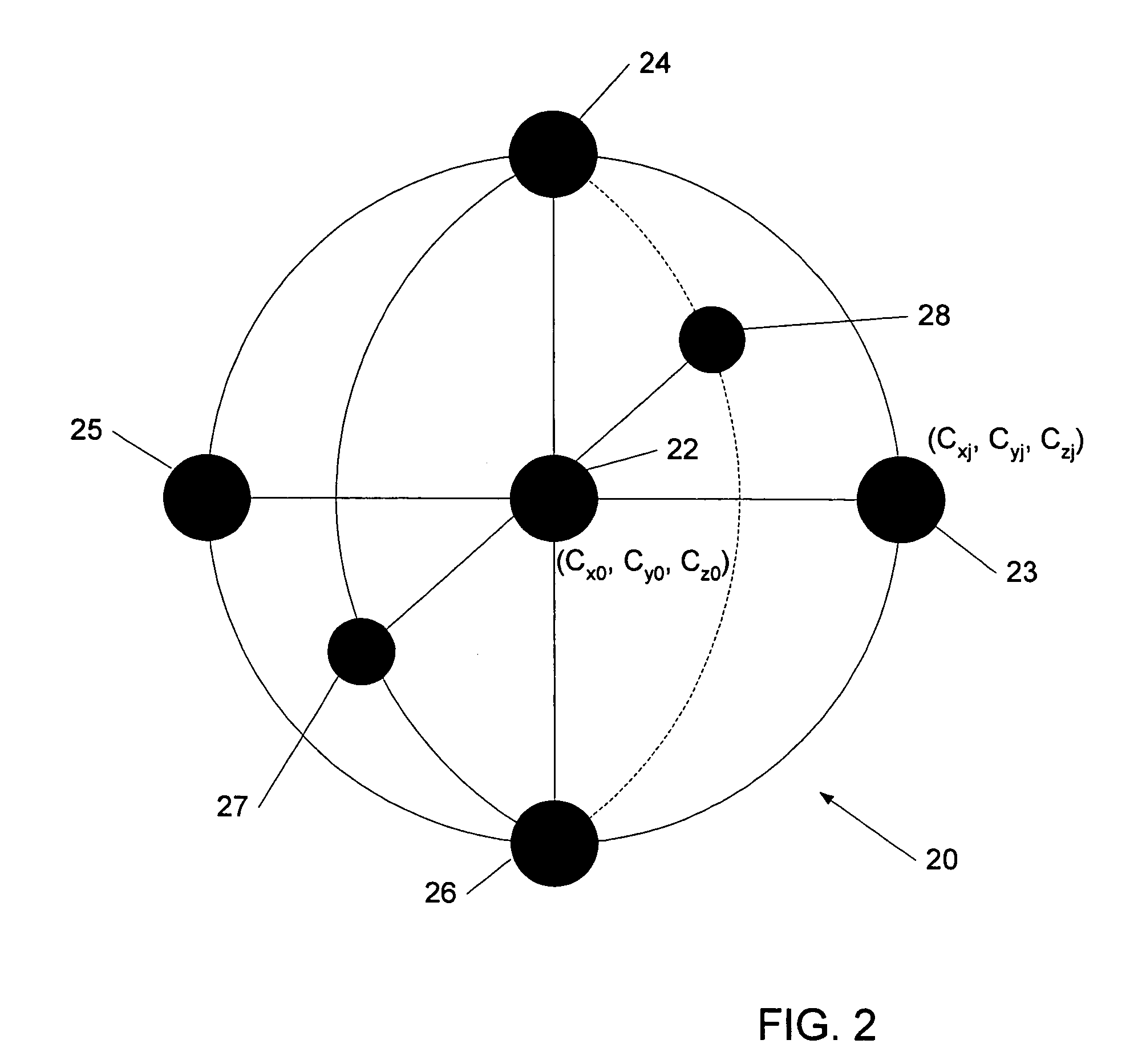
[0029]Supersonic projectile trajectories are estimated solely from projectile shockwave arrival times measured by several closely spaced sensors distributed throughout a “small” measurement volume referred to as antenna. A measurement volume is considered small if the sensor spacing is 2 meters or less. Once the projectile's trajectory is identified, the location of the shooter is known except for distance back along the trajectory. This distance can be found if the antenna also obtains the arrival time of the muzzle blast sound. However, the muzzle blast is not always detectable, so that an accurate shockwave-only solution is essential for determining the trajectory.

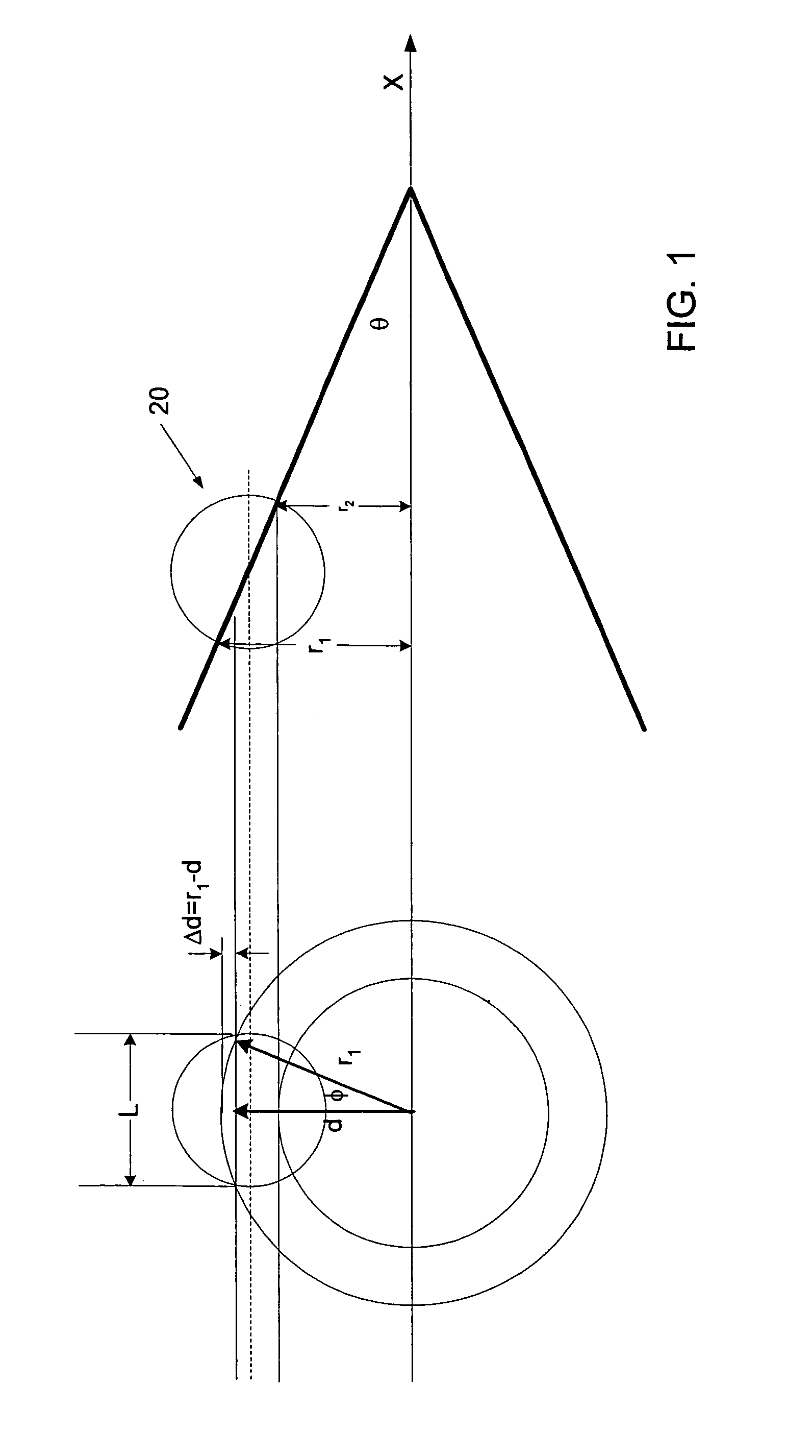
[0030]Referring now to FIG. 1, the shockwave surface is considered to be an expandin...


PUM


Abstract

Systems and methods for locating the shooter of supersonic projectiles based on shockwave-only measurements are described. Muzzle blast signals are neither sought nor required. The system uses at least five, preferably seven, acoustic sensors that are spaced apart at least 1 meter. The sensor signals are acquired with a time resolution in the order of microseconds and processed to find and disambiguate the shockwave arrival angle unit vector. Two different Time-Difference-Of-Arrival (TDOA) measurement techniques are described, with one technique using counters in each signal channel and the other technique using cross-correlation between signal channels. A genetic algorithm can be used to efficiently disambiguate the results.

Description

GOVERNMENT CONTRACT[0001]The U.S. Government has a paid-up license in this invention and the right in limited circumstances to require the patent owner to license others on reasonable terms as provided for by the terms of Contract No. HR0011-04-C-0035 awarded by DARPA ATO.BACKGROUND OF THE INVENTION[0002]The present invention relates to law enforcement technologies and security, and more particularly to methods and systems for determining the origin and direction of travel of supersonic projectiles based on shockwave-only information.[0003]Systems and methods are known that can determine the general direction and trajectory of supersonic projectiles, such as bullets and artillery shells by measuring parameters associated with the shockwave generated by a projectile. One such system, described in U.S. Pat. No. 5,241,518 includes at least three spaced-apart sensors, with each sensor incorporating three acoustic transducers arranged in a plane. The sensors generate signals in response ...

Claims


Application Information

Patent Timeline
Patent Type & Authority Patents(United States)
IPC IPC(8): G01S5/18G01S3/80
CPCF41J5/06G01S3/808G01S5/22Y10S367/906
Inventor BARGER, JAMES EDWINMILLIGAN, STEPHEN DOUGLASBRINN, MARSHALL SETHMULLEN, RICHARD J.
Owner RAYTHEON BBN TECH CORP
Why Eureka
Try Eureka