Locking device for steering shaft and steering apparatus having the device

a technology of locking device and steering shaft, which is applied in the direction of mechanical control devices, anti-theft devices, instruments, etc., can solve the problems of increasing the difficulty of ensuring and the inability of the conventional vehicle having an electric power steering apparatus thus constructed to meet the recent demand for an increase in the stroke length, so as to achieve the effect of increasing the stroke length of the impact absorbing mechanism

Inactive Publication Date: 2006-10-31
KOYO SEIKO CO LTD
View PDF22 Cites 8 Cited by
  • Summary
  • Abstract
  • Description
  • Claims
  • Application Information

AI Technical Summary

Benefits of technology

[0013]Another object of the invention is to provide a locking device for a steering shaft and a steering apparatus having the locking device in which a side face of an engagement part is not damaged even if large torque is repeatedly applied to the steering wheel.
[0018]With this locking device for a steering shaft, in which the engagement part is formed on the side face of the driven gear of the reduction gear mechanism, and not on the peripheral surface of the steering shaft, an enough thickness of the engagement part can be ensured. Consequently, the side face of the engagement part is not damaged even if large torque is repeatedly applied to the steering shaft.
[0022]With this steering apparatus, the stroke length of the impact absorbing mechanism can be increased in comparison with conventional apparatuses. Moreover, the side face of the engagement part is not damaged even if large torque is repeatedly applied to the steering shaft. Furthermore, the steering shaft can be locked electrically.

Problems solved by technology

In a vehicle provided with an electric power steering apparatus in which a driven gear is fastened at the middle of a lower shaft of a steering shaft as described above, it is more difficult to ensure a stroke length of the impact absorbing mechanism, in comparison with a vehicle which does not have a steering assist motor or a reduction gear mechanism at the middle of the steering shaft.
Consequently, a conventional vehicle having an electric power steering apparatus thus constructed can not meet a recent demand for an increase in stroke length to further enhance the safety at the time of collision.

Method used


Image

  • Locking device for steering shaft and steering apparatus having the device
  • Locking device for steering shaft and steering apparatus having the device
  • Locking device for steering shaft and steering apparatus having the device

Examples


Embodiment Construction

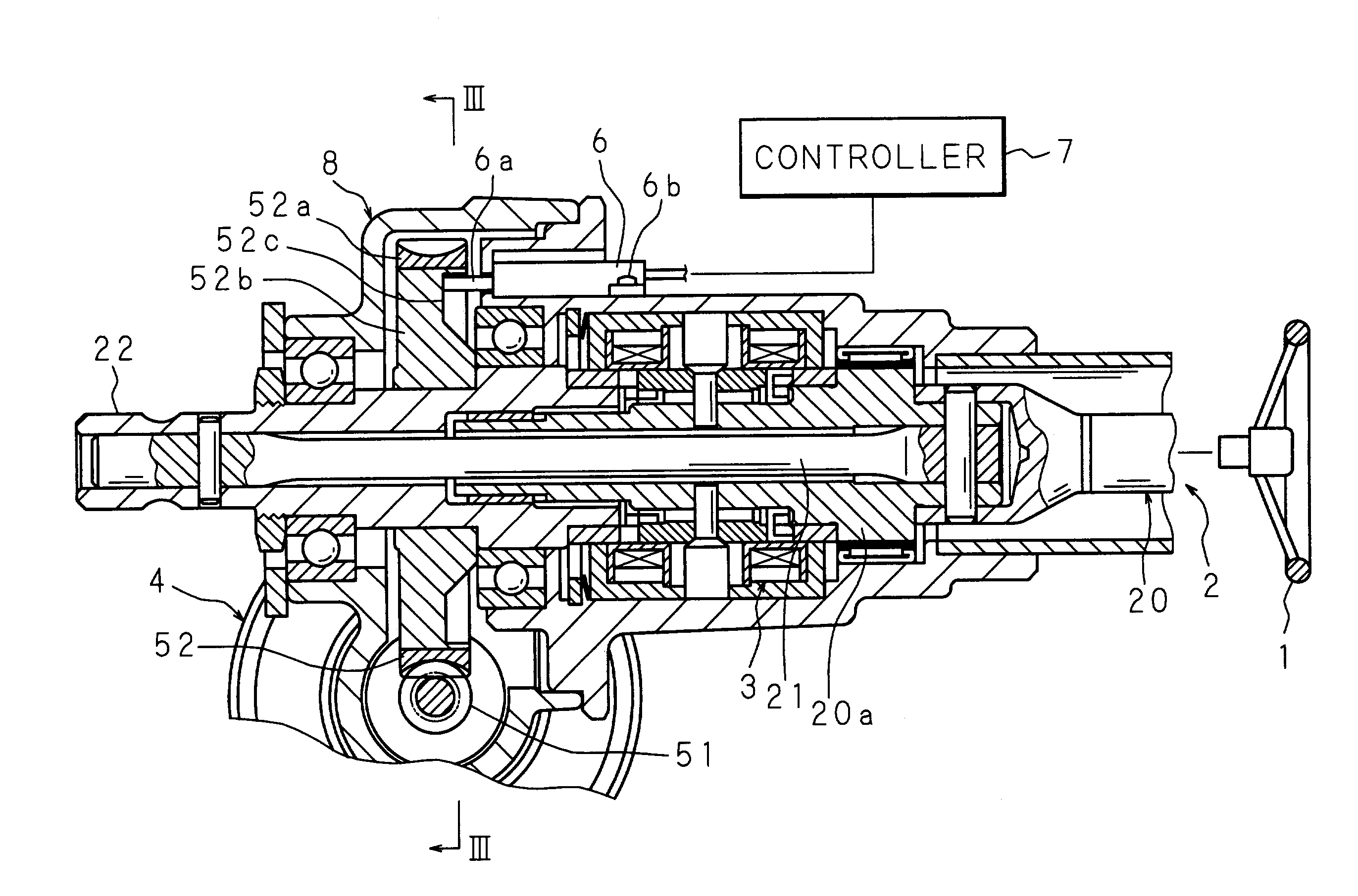
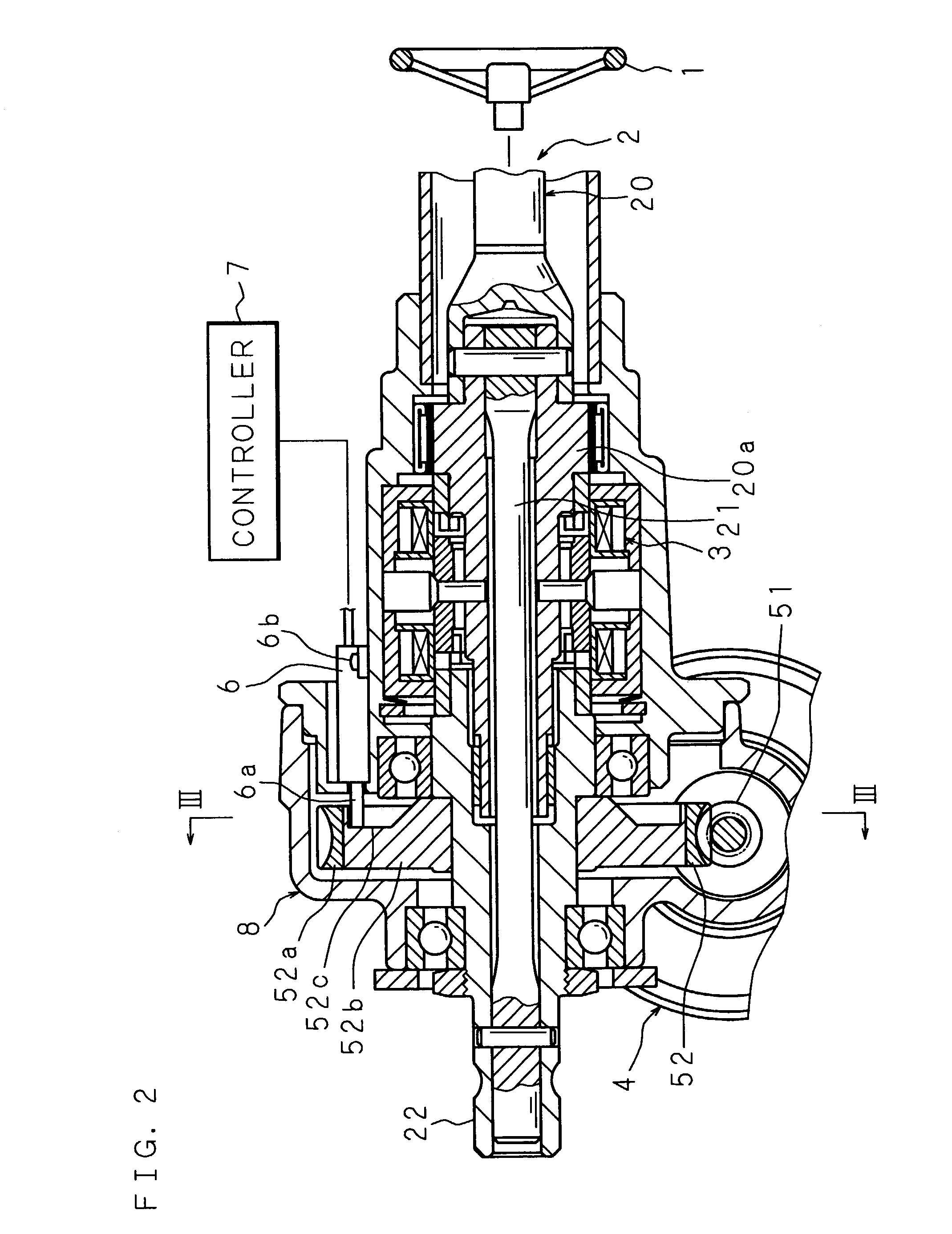
[0028]The following description will explain the present invention in detail with reference to the drawings illustrating an embodiment thereof. FIG. 2 is a sectional view of an essential part of a locking device for a steering shaft according to the present invention, which illustrates a state where the steering shaft is locked by the locking device; and FIG. 3 is a sectional view illustrating an essential part, taken along the line III—III in FIG. 2.

[0029]The reference numeral 2 in figures indicates a steering shaft. The steering shaft 2 is composed of an upper shaft 20, a cylinder part 20a, a torsion bar 21 and a lower shaft 22. The upper end of the upper shaft 20 is connected with a steering wheel 1. A portion of the upper shaft 20 covering a predetermined length from the lower end is formed cylindrically and fitted on the upper end of the cylinder part 20a. An upper portion of the torsion bar 21 is inserted in the cylinder part 20a. The upper end of the cylinder part 20a and the...


PUM


Abstract

Engagement parts 52c of the locking device for a steering shaft are formed on a side face of a driven gear of a reduction gear mechanism which is fastened to a steering shaft 2. Since a locking part 6a is arranged near the reduction gear mechanism, elements related to a locking function can be removed from the key cylinder of the engine key, so that the key cylinder of the engine key can be downsized, or can be arranged in another position. Consequently, even in a state where a reduction gear mechanism, a steering assist motor and the like are arranged in the middle of the steering shaft, a longer stroke of the impact absorbing mechanism in comparison with conventional mechanisms can be ensured, utilizing a decrease in length of the downsized or reduced key cylinder in the axial direction of the steering shaft 2.

Description

BACKGROUND OF THE INVENTION[0001]1. Field of the Invention[0002]The present invention relates to a locking device for locking a steering shaft so as to keep the shaft from turning while the car is not used, and to a steering apparatus provided with the locking device.[0003]2. Description of Related Art[0004]For preventing theft during parking, cars are provided with a locking device for locking a steering shaft which is used for transmitting rotation of a steering wheel to a steering mechanism.[0005]FIG. 1 is a sectional view illustrating an essential part of a conventional locking device for a steering shaft. As disclosed in Japanese Patent Application Laid-Open No. 57-191149 (1982), for example, a conventional locking device has a key cylinder 109 of an engine key which is fastened to an upper portion of an upper shaft housing 107 for supporting a steering shaft 101 connected to a steering wheel 100. The key cylinder 109 is connected with a lock key 108 which slides into the upper...

Claims


Application Information

Patent Timeline
Patent Type & Authority Patents(United States)
IPC IPC(8): E05B65/12B60R25/021B60R25/0215B62D5/04E05B81/04E05B83/00
CPCB60R25/02B62D5/0409Y10T70/5659Y10T70/5956
Inventor KINME, SHIGETAKAHOSOMI, NORIOAOTA, KENICHI
Owner KOYO SEIKO CO LTD
Why Eureka
Try Eureka