

Air intake apparatus for internal combustion engine
a technology for air intake apparatus and internal combustion engine, which is applied in mechanical equipment, cylinders, machines/engines, etc., can solve the problems of less effective in promoting combustion, limited operation condition allowing gas flow strengthening by closing the intake control valve, and deterioration of fuel efficiency or emission, etc., to achieve the effect of strengthening airflow
- Summary
- Abstract
- Description
- Claims
- Application Information
AI Technical Summary
Benefits of technology
Problems solved by technology
Method used
Image

Examples
embodiment 1
[0034]In the following, an air intake apparatus for an internal combustion engine according to Embodiment 1 of the present invention will be described. It is noted that the internal combustion engine shown below will be described as a spark ignition type gasoline engine. In addition, an injector provided in the engine may be an injector for injecting a fuel into an intake port, or an injector for injecting the fuel into the cylinder. Alternatively, an engine having both injectors may be adopted.
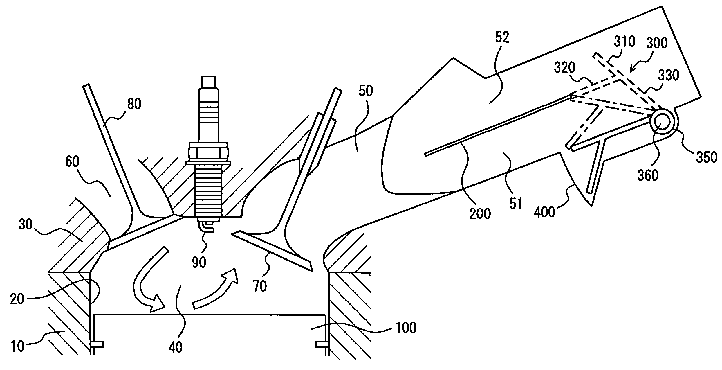
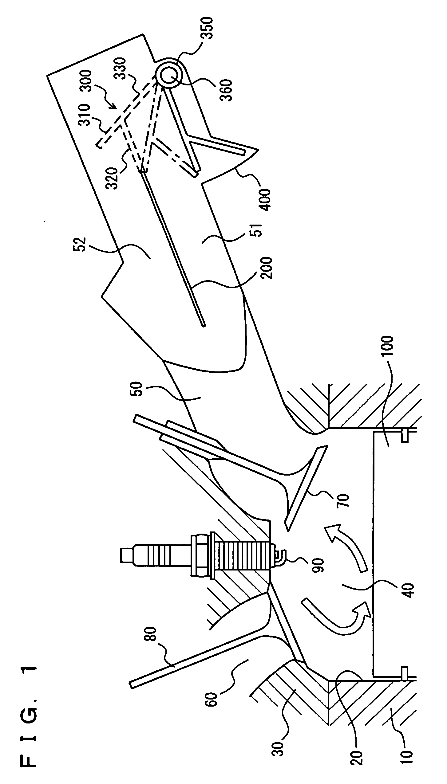
[0035]FIG. 1 shows an overall structure of the air intake apparatus for an internal combustion engine according to the present embodiment applied as an air intake apparatus for an in-cylinder direct injection spark ignition type gasoline engine. The air intake apparatus aims to strengthen the tumble as the gas flow.
[0036]As shown in FIG. 1, a cylindrically-shaped cylinder 20 is formed in a cylinder block 10, and a pent roof type combustion chamber 40 is provided in a cylinder head 30 covering...
embodiment 2
[0059]In the following, an air intake apparatus for an internal combustion engine according to Embodiment 2 of the present invention will be described. In the air intake apparatus for the internal combustion engine according to the present embodiment, intake control valve 300 provided in the lower first flow path in the air intake apparatus for the internal combustion engine according to Embodiment 1 described previously is replaced with an intake control valve 302 provided in the upper second flow path. As the structure of the engine or the like is otherwise similar to that in Embodiment 1 described above, detailed description thereof will not be repeated.
[0060]As shown in FIG. 5, in the present embodiment as in Embodiment 1, partition wall 200 is provided along the longitudinal direction of intake port 50, so as to cross-sectionally partition intake port 50 into two upper and lower sections.
[0061]In the portion where partition wall 200 is present, the space within intake port 50 i...
embodiment 3
[0072]In the following, an air intake apparatus for an internal combustion engine according to Embodiment 3 of the present invention will be described. In the air intake apparatus for the internal combustion engine according to the present embodiment, an intake control valve 500 having a shape different from intake control valve 300 in the air intake apparatus for the internal combustion engine according to Embodiment 1 and intake control valve 302 in the air intake apparatus for the internal combustion engine according to Embodiment 2 described previously is provided. As the structure of the engine or the like is otherwise similar to that in Embodiment 1 described above, detailed description thereof will not be repeated.
[0073]As shown in FIGS. 6 and 7, in the present embodiment as in Embodiment 1, partition wall 200 is provided along the longitudinal direction of intake port 50, so as to cross-sectionally partition intake port 50 into two upper and lower sections. It is noted here ...
PUM
 Abstract
Description
Claims
Application Information