
Liquid warming device with basin

a technology of liquid heating device and basin, which is applied in the direction of heating types, instruments, furniture, etc., can solve the problems of increasing the risk of surgical wound infection, increasing the vascular resistance, and the range of adverse effects, and achieve good thermal contact

Active Publication Date: 2006-10-31
C CHANGE SURGICAL
View PDF16 Cites 59 Cited by
  • Summary
  • Abstract
  • Description
  • Claims
  • Application Information

AI Technical Summary

Benefits of technology

The solution provides precise temperature control of sterile fluids, reduces the risk of contamination, and ensures safe heating without compromising the integrity of the sterile field, enhancing surgical safety and reducing costs by allowing reusable basin components.

Problems solved by technology

Clinical studies have indicated that a range of adverse consequences arise from a change in body core temperature as little as one to three degrees Celsius.
The adverse consequences from mild perioperative hypothermia include hypertension and increased vascular resistance, cardiac events, coagulopathy, an increase risk of surgical wound infections, and delays in the body's ability to remove drugs from its systems.
An additional potential adverse consequence is shivering which can increase metabolic rate up to 500% and thus increase demands for oxygen and the need to clear carbon dioxide.
It is also recognized that having the heater apply so much heat that it damages the container used to hold the fluid is undesirable.
Use of a heater that can expose personnel to heated surfaces that are hot enough to cause injury is undesirable and in some cases contrary to governmental regulations.
An additional problem in the prior art relates to maintaining the integrity of the sterile field.
Any breach that might indicate that the sterile field has become contaminated is taken very seriously.
A breach that is undiscovered for a period of time is especially troublesome as it is difficult to assess when the breach was created and whether it caused the patient to be exposed to contaminants while vulnerable during surgery.
Thus, problems associated with the recognized risk of a breach in a sterile drape have led others to develop various ways of reducing this risk or at least quickly detecting the breach.
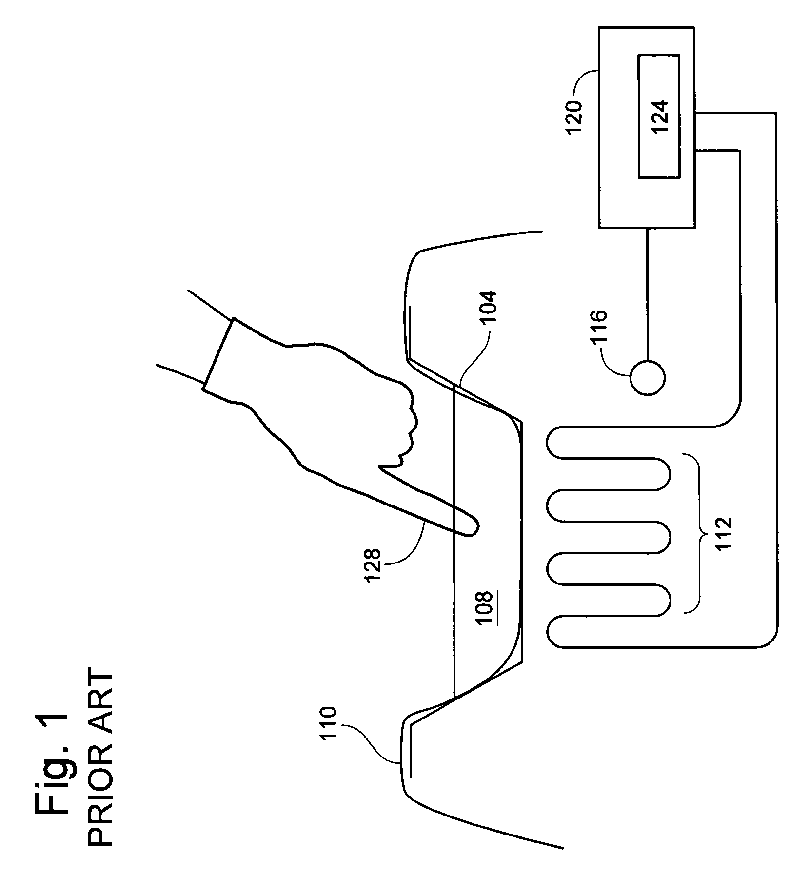
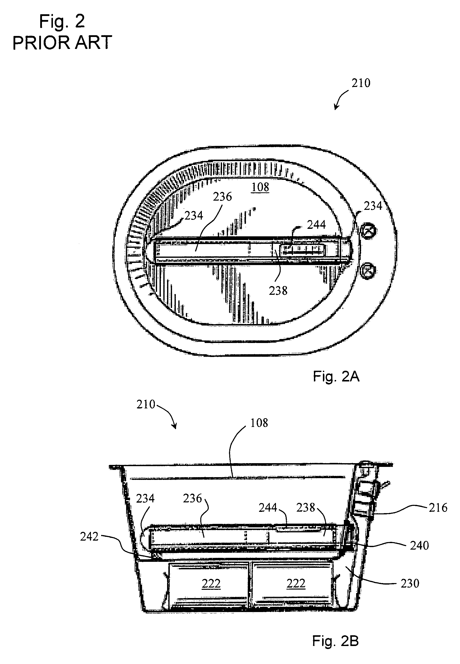
But, it is hard to see a way to sterilize the '033 device as reuse from surgery to surgery would require a method of reliably sterilizing the heater assembly 234 along with the surface of the bowl that would come in contact with the sterile fluid 108.
A second obvious problem with the solution proposed in the '033 patent is that the heater assembly 234 is simply in the way.
As noted above, even if the risk of causing a failure to the electrical components or seals is slight, such a risk diminishes the peace of mind of the surgical staff.
Adding various detectors to quickly detect various failure modes might increase peace of mind somewhat but at yet another set of added costs to the single-use disposable unit.
The prior art lacks a solution for a fluid heating device using a removable basin that provides the benefits of using the actual temperature of the sterile fluid as an input to the control system without incurring the risks and problems inherent in the use of such a temperature probe.

Method used


Image

  • Liquid warming device with basin
  • Liquid warming device with basin
  • Liquid warming device with basin

Examples


Embodiment Construction

[0034]The present invention will now be described more fully hereinafter with reference to the accompanying drawings, in order to disclose selected embodiments. This invention may, however, be embodied in many different forms and should not be construed as limited to the embodiments set forth herein; rather, these embodiments are provided so that this disclosure will be thorough and complete, and will fully convey the scope of the invention to those skilled in the art. Like numbers refer to like elements throughout.

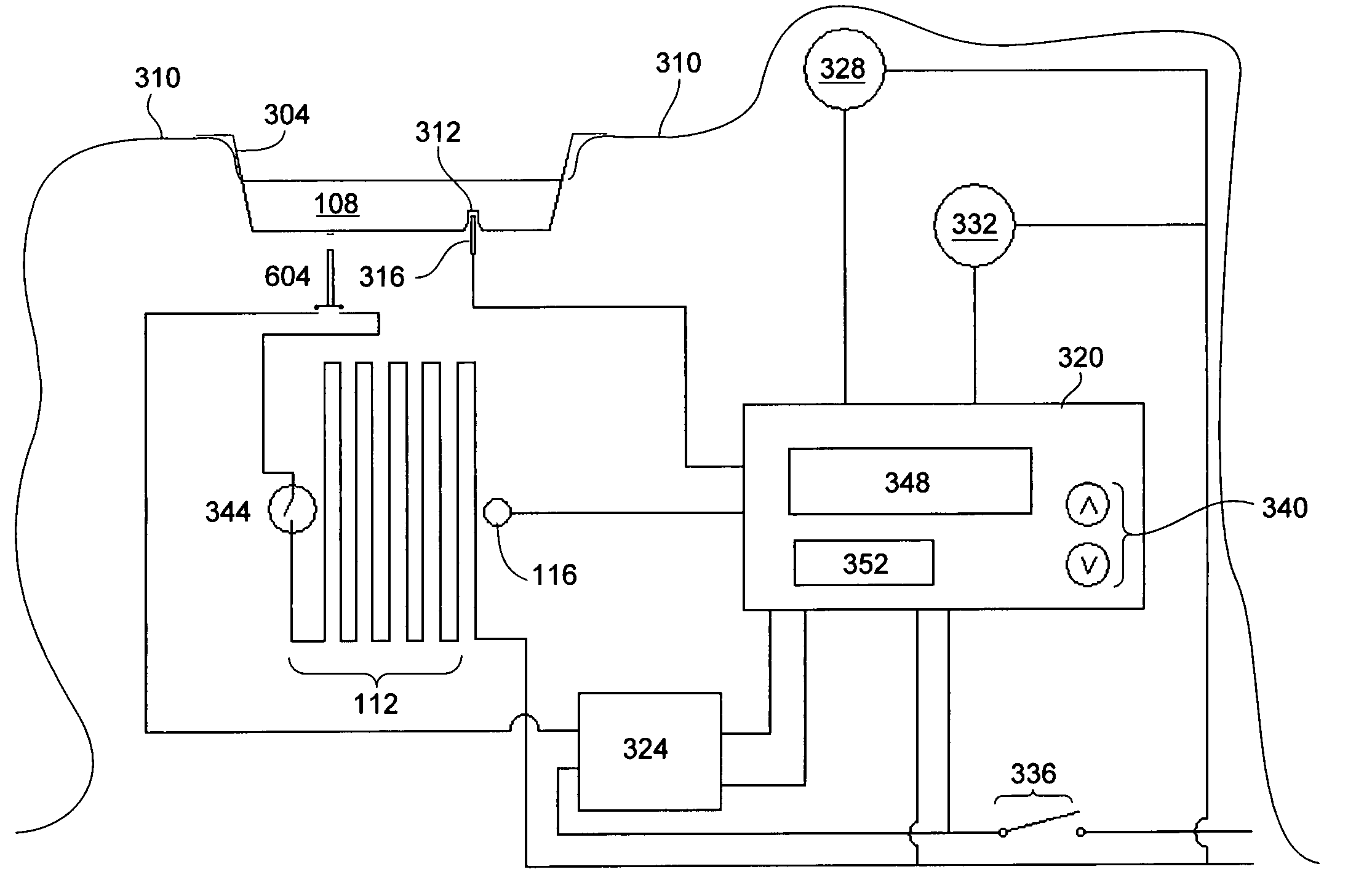
[0035]FIG. 3 illustrates a first embodiment of the present invention. The sterile fluid 108 is inside modified basin 304 with integral thermocouple well 312 and temperature sensor 316. The heater 112 selectively applies heat that is transferred to the basin 104 and the fluid 108. The fluid warming device has a main on / off switch 336. Some heating elements come with a mechanical thermostat 344 such as a bimetallic thermostat to provide a secondary protection against a fail...


PUM


Abstract

A liquid warming device for heating sterile fluids in a removable basin is described with emphasis on the properties of the basin interaction with the liquid warming device and with a drape that works with the basin to maintain a sterile field above the drape and the top of the basin. The interactions between a temperature sensor and a temperature well integrated in the removable basin are disclosed. Also disclosed are various desirable aspects for a control system for a liquid warming device are provided.

Description

[0001]This application claims priority to and incorporates by reference herein, two provisional patent applications: U.S. Provisional Patent Application 60 / 603,957 for Heating Element for Liquid Warming Device filed Aug. 24, 2004 and U.S. Provisional Patent Application 60 / 603,956 for Liquid Warming Device and Control System filed Aug. 24, 2004. A basin suitable for use with the present invention is shown in pending U.S. Design patent application Ser. No. 29 / 226,136 filed Mar. 24, 2005 for Hospital Basin with Channel. This application claims priority to the Ser. No. 29 / 226,136 application and incorporates it by reference.[0002]Another application with common assignee is co-pending with the present application. The co-pending application is for a Heating Element for Liquid Warming Device with U.S. Ser. No. 11 / 209,430. The inventive aspects of heating elements disclosed in that application can be advantageously used with the present invention. The co-pending application is incorporated...

Claims


Application Information

Patent Timeline
Patent Type & Authority Patents(United States)
IPC IPC(8): F27D11/00A61B18/14A61F7/12G05D23/12
CPCG05D23/2028G05D23/2208A61B2019/0298G05D23/1909G05D23/1931G05D23/20G05D23/22A61B2050/0018A61B46/10
Inventor KAMMER, PATRICKRACKERS, KEVIN JOSEPH
Owner C CHANGE SURGICAL
Learn More