Temperature activated pressure relief mechanism for flashlights and batteries

a technology of pressure relief mechanism and flashlight, which is applied in the direction of vent arrangement, lighting and heating apparatus, cell components, etc., can solve the problems of high cost, safety risk, and many types of batteries that emit flammable or explosive gas, and achieve the effect of low cos

Inactive Publication Date: 2006-10-31
W T STOREY
View PDF9 Cites 3 Cited by
  • Summary
  • Abstract
  • Description
  • Claims
  • Application Information

AI Technical Summary

Benefits of technology

[0011]There remains a need for a sealed flashlight which is essentially impervious to water so that it can be used at significant depths but which will permanently and dependably open a reliable low cost and simple fusible plug vent at a temperature below that at which the internal battery vent opens so that the flashlight itself does not become a containment vessel that might burst in a fire from the gas pressure released by the battery.
[0020]Preferably, said eyelet opening has a diameter of approximately 1 / 16 inch which in many applications will be effective and have the lowest cost.

Problems solved by technology

It is well known that many types of batteries emit flammable or explosive gas.
However, there are also other types of batteries, such as for example, lithium-iron disulfide batteries, which do not produce or emit any significant quantities of flammable or explosive gas under normal operating conditions which might pose a safety risk which would require continuous venting.
A potential problem which has not been adequately addressed in the past is that even the safer non-gas producing batteries may under extreme conditions, such as a fire or very high temperatures, develop high pressures and explode.
The existing flashlight vents, valves and permeable membranes are overly complex, potentially unreliable and overly expensive to employ and are not necessarily designed to function in this type of extreme high temperature situation.

Method used


Image

  • Temperature activated pressure relief mechanism for flashlights and batteries
  • Temperature activated pressure relief mechanism for flashlights and batteries
  • Temperature activated pressure relief mechanism for flashlights and batteries

Examples


Embodiment Construction

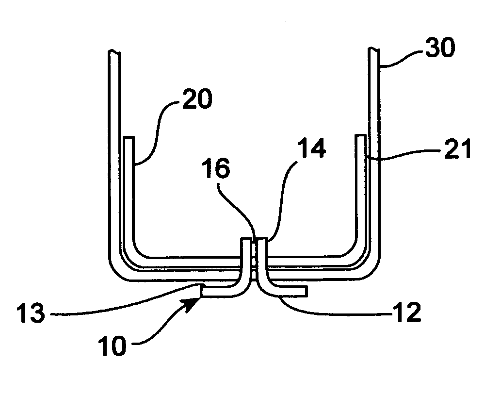
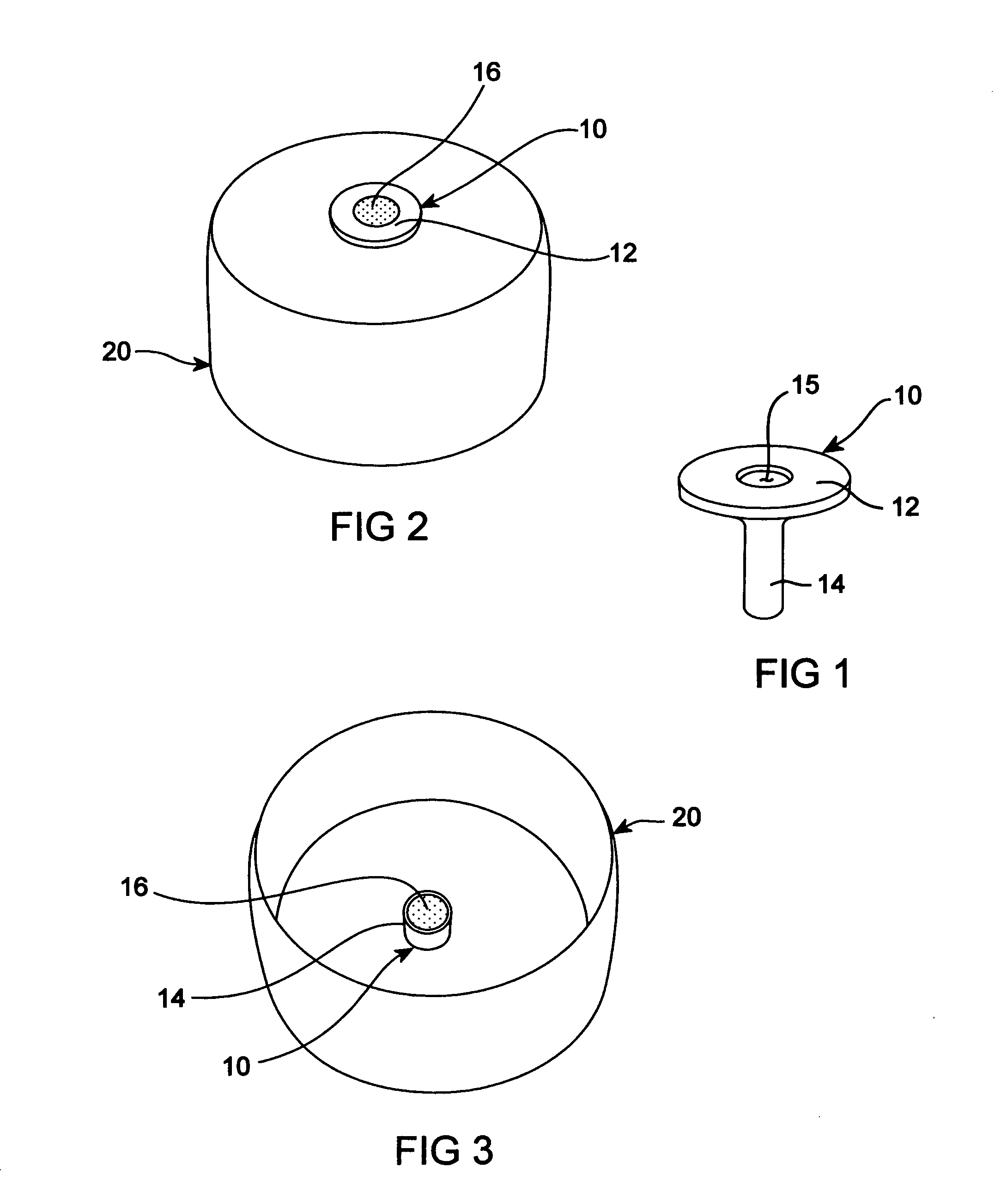
[0026]Referring to FIGS. 1–3, a copper eyelet 10 which has a stem portion 14 and a flange portion 12 is shown. An eyelet opening 15 extends from the center of the flange portion 12 through the stem portion 14.

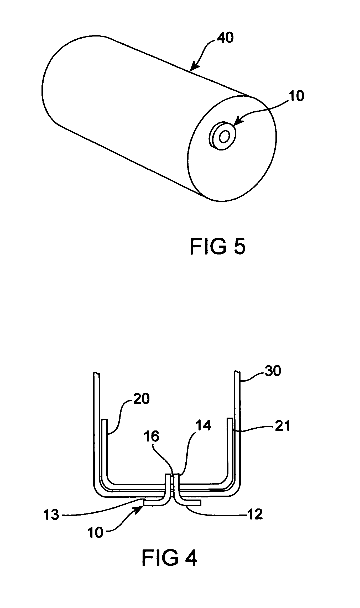
[0027]Referring to FIGS. 2–3, an eyelet is shown after it has been pressed and fit into a stainless steel end cap 20. In FIG. 4, a flashlight housing 30 is shown which includes a stainless steel end cap 20 pressed into said housing and sealed with a silicone sealant 21.

[0028]The eyelet 10 is sealed to said housing with a non-corrosive sealant 13 selected from the group comprising: anaerobic sealants (such as Locktite™); epoxies; solvated plastics; and polysulfides. Locktite is presently preferred although any of these materials will function as sealant as the press fitting operation provides a tight fit which avoids the need for an adhesive material.

[0029]Opening 15 of eyelet 10 is filled with an alloy material 16 which consists of approximately 52.5% by weight of Bismuth (Bi),...


PUM

PropertyMeasurementUnit
melting temperatureaaaaaaaaaa
melting temperaturesaaaaaaaaaa

Abstract

A temperature activated pressure relief mechanism for a flashlight or other battery containing device includes a watertight sealed flashlight housing which has an opening which extends from an outer surface to and inner surface of the housing. A metallic eyelet having an eyelet opening and having a cylindrical body sized to fit is placed tightly into the housing opening. A fusible plug of a suitable alloy material placed into said eyelet opening so that when said alloy material reaches the alloy melting point, said material will melt and flow at least partially out of the eyelet opening allowing gas pressure from within the sealed flashlight housing to vent to outside the sealed housing through the eyelet opening.

Description

BACKGROUND OF THE INVENTION[0001]1. Field of the Invention[0002]The present invention relates to a temperature activated pressure relief mechanism for flashlights and other sealed battery operated devices and for batteries. More specifically, it relates to a temperature activated pressure relief mechanism which prevents explosion of a battery or sealed flashlight containing a battery which is exposed to a high temperature environment such as a fire.[0003]2. Description of the Prior Art[0004]It is well known that many types of batteries emit flammable or explosive gas. Because of this, many flashlight designs include gas vents, membranes or one-way valves to allow the discharge of such gas from a sealed flashlight container. It is even a specific requirement of an Underwriters Laboratory standard, namely, UL STD 913 on apparatus for use in hazardous environments which requires (18.1.3) “Compartments containing batteries which emit flammable gas shall be ventilated to prevent accumula...

Claims


Application Information

Patent Timeline
Patent Type & Authority Patents(United States)
IPC IPC(8): F21V25/10F21L4/00H01M2/12
CPCF21L4/005F21V15/01F21V31/03H01M2/12H01M2/1282F21V25/10H01M50/30H01M50/375Y02E60/10
Inventor STOREY, WILLIAM T.
Owner W T STOREY
Why Eureka
Try Eureka