Interactive simulation of a pneumatic system

a pneumatic system and simulation technology, applied in the field of computerized simulation systems, can solve the problems of limited use of diagnostic instruments, and limited use of treatment tools

Inactive Publication Date: 2006-10-31
UNIV OF FLORIDA RES FOUNDATION INC
View PDF13 Cites 72 Cited by
  • Summary
  • Abstract
  • Description
  • Claims
  • Application Information

AI Technical Summary

Benefits of technology

[0015]In accordance with the inventive arrangements, a pneumatic system can be divided into logical component sections. Each of the logical component sections can be visually rendered in a graphical user interface. Also, user modification of control element settings in the logical component sections can be permitted. Subsequently, gas flows within the logical component sections can be animated by rendering individual gas molecule images in the component sections. Each individual gas molecule image can be coupled to, or instantiated visually by, computer-readable code comprising an animation logic script for directing, or otherwise causing, not only the direction of the visual animation

Problems solved by technology

A century ago, diagnostic tools barely existed, while treatment tools were restricted to purely mechanical devices.
The study of control systems gave rise in the mid twentieth century to more complex diagnostic and treatment tools in which the electronic and manual operation of valves and switches permitted the selective application of forces about the patient.
As it will be recognized by the skilled artisan, however, both the operation of the instrument, and particular the use of the GUI can be extraordinarily complex.
Yet, the extraordinary complexity of modern electronic control systems can produce an unacceptable risk of human error in the operation of the instrument.
Moreover, it is well known that clinicians often lack either or both the free time and the motivation to read an instrument manual or to attend a class directed to the use of a medical instrument.
The initial process can be quite stressful and often can involve trial and error manipulation of instrument controls while observing the resulting effect of the manipulation.
While such trial and error experimentation is not possible with an actual device and actual patient, the simulation allows the user to experiment with many different scenarios without placing a patient at risk.
The anesthesia machine as a pneumatic system is perhaps one of the most complex medical instruments and requires significant training in its operation.
Yet, the mechanical aspects of the

Method used


Image

  • Interactive simulation of a pneumatic system
  • Interactive simulation of a pneumatic system
  • Interactive simulation of a pneumatic system

Examples


Embodiment Construction

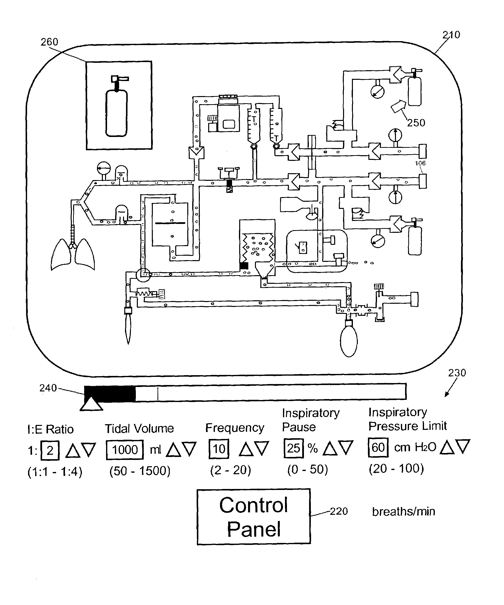
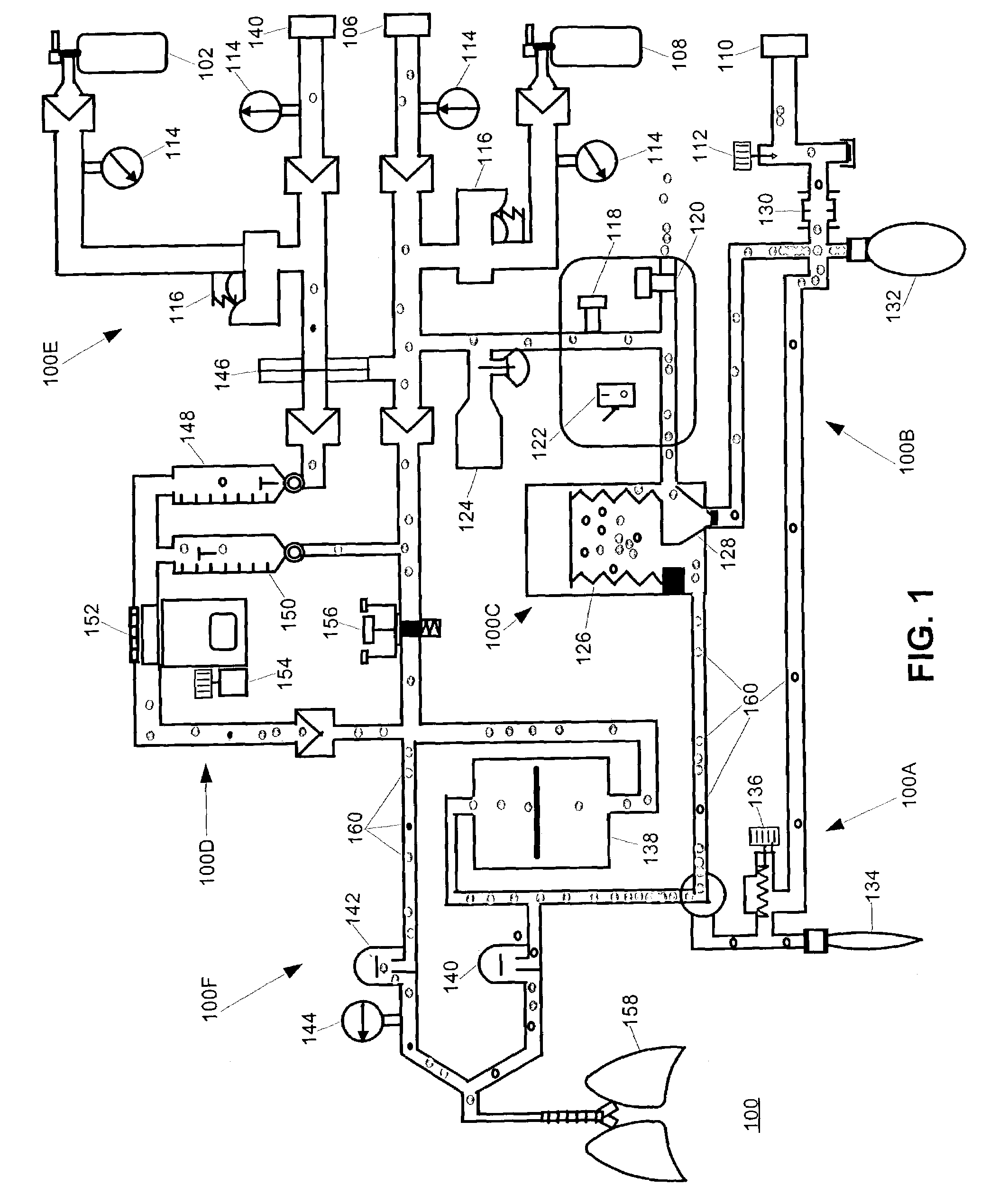
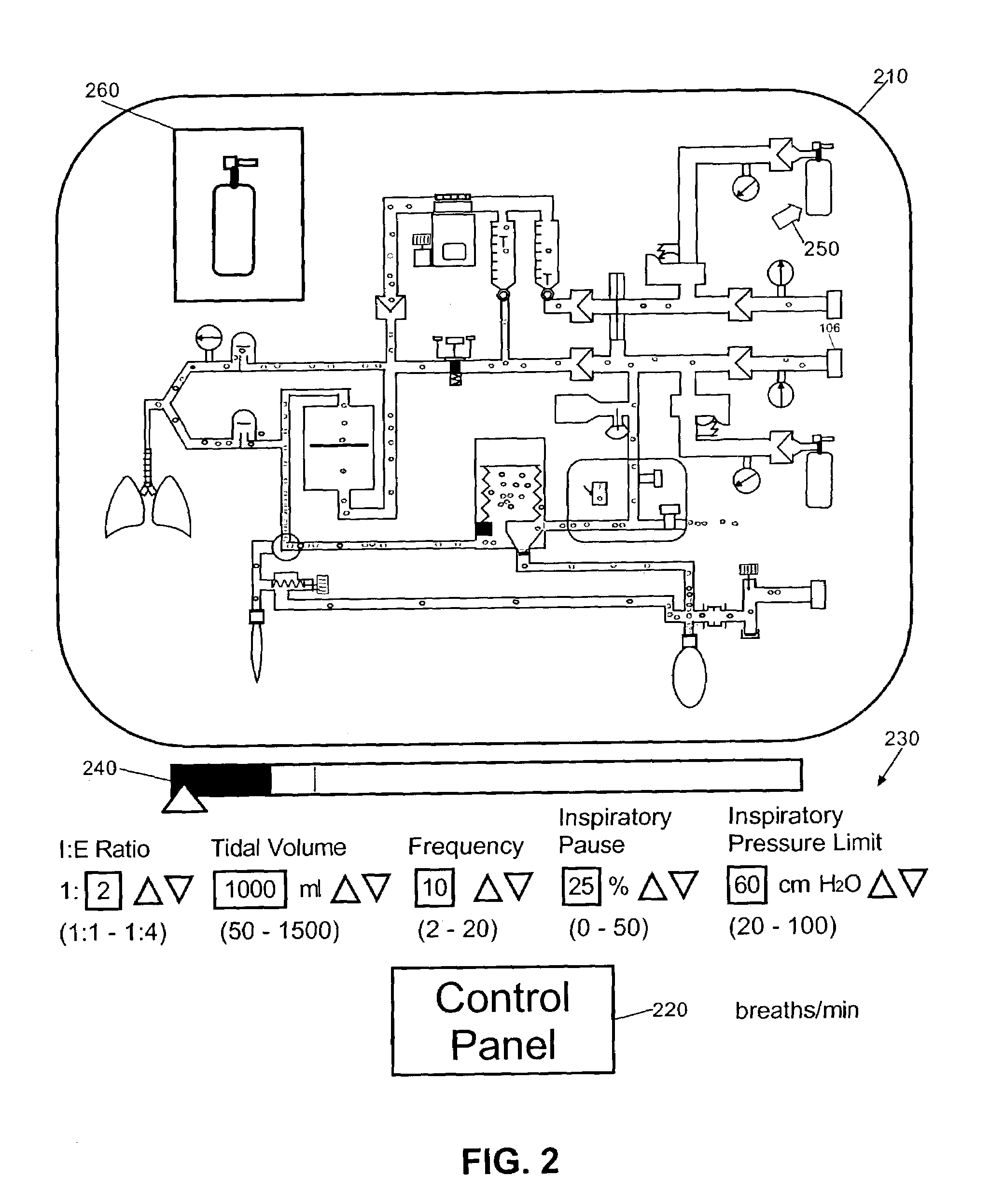
[0029]The present invention is a pneumatic simulation system, method and apparatus. In accordance with the present invention, a conceptual view of a pneumatic system can be rendered in a graphical user interface. The pneumatic system can include, as an example, an, anesthesia machine, though the invention is not so limited and other systems can suffice, for instance an ICU ventilator. In any event, elements of the conceptual view of the pneumatic system can be activated, deactivated, or otherwise manipulated through the user interface. Resulting gas flows within the pneumatic system can be simulated graphically in the conceptual view.

[0030]More particularly, iconic representations of the gases in the pneumatic system can be animated through the concurrent presentation of individual gas molecule images within conduit sections of the pneumatic system. Each gas molecule image can be animated by way of a corresponding animation script. Each animation script can determine a direction and...


PUM


Abstract

A method, system and apparatus for simulating a pneumatic system. The method can include dividing a pneumatic system into logical component sections. Each of the logical component sections can be visually rendered in a graphical user interface. Also, user modification of control element settings in the logical component sections can be permitted. Subsequently, gas flows within the logical component sections can be animated using individually rendered gas molecule icons coupled to corresponding animation scripts. Each of the scripts can determine an animation direction and animation rate for a corresponding one of the gas molecule icons. In particular, the actual pneumatic system can be an anesthesia machine.

Description

CROSS-REFERENCE TO RELATED APPLICATIONS[0001]Pursuant to 35 U.S.C. § 119(e), this patent application is a continuation-in-part of U.S. Provisional Patent Application No. 60 / 384,040, filed on May 29, 2002, the contents of which are incorporated herein by reference.BACKGROUND OF THE INVENTION[0002]1. Statement of the Technical Field[0003]The present invention relates to computerized simulation systems. More specifically, the invention relates to a method, system and apparatus for the interactive real-time simulation of a pneumatic system.[0004]2. Description of the Related Art[0005]Medical instruments range from the venerable scalpel to ultra-complex imaging systems. Each medical instrument includes an inherent utility in the field of health care diagnostics and medical treatment. A century ago, diagnostic tools barely existed, while treatment tools were restricted to purely mechanical devices. The study of control systems gave rise in the mid twentieth century to more complex diagnos...

Claims


Application Information

Patent Timeline
IPC IPC(8): G09B25/00G09B23/12G09B23/30
CPCG09B23/12G09B23/30
Inventor LAMPOTANG, SAMSUNLIZDAS, DAVID ERIKLIEM, EDWIN BOEDIONO
Owner UNIV OF FLORIDA RES FOUNDATION INC
Why Eureka
Try Eureka