Majority logic circuit

Inactive Publication Date: 2006-10-31
NATIONAL SECURITY AGENCY
View PDF7 Cites 12 Cited by
  • Summary
  • Abstract
  • Description
  • Claims
  • Application Information

AI Technical Summary

Problems solved by technology

This method requires extensive use of processor resources and requires a determination of which return addresses are valid and which are i

Method used


Image

  • Majority logic circuit
  • Majority logic circuit
  • Majority logic circuit

Examples


Embodiment Construction

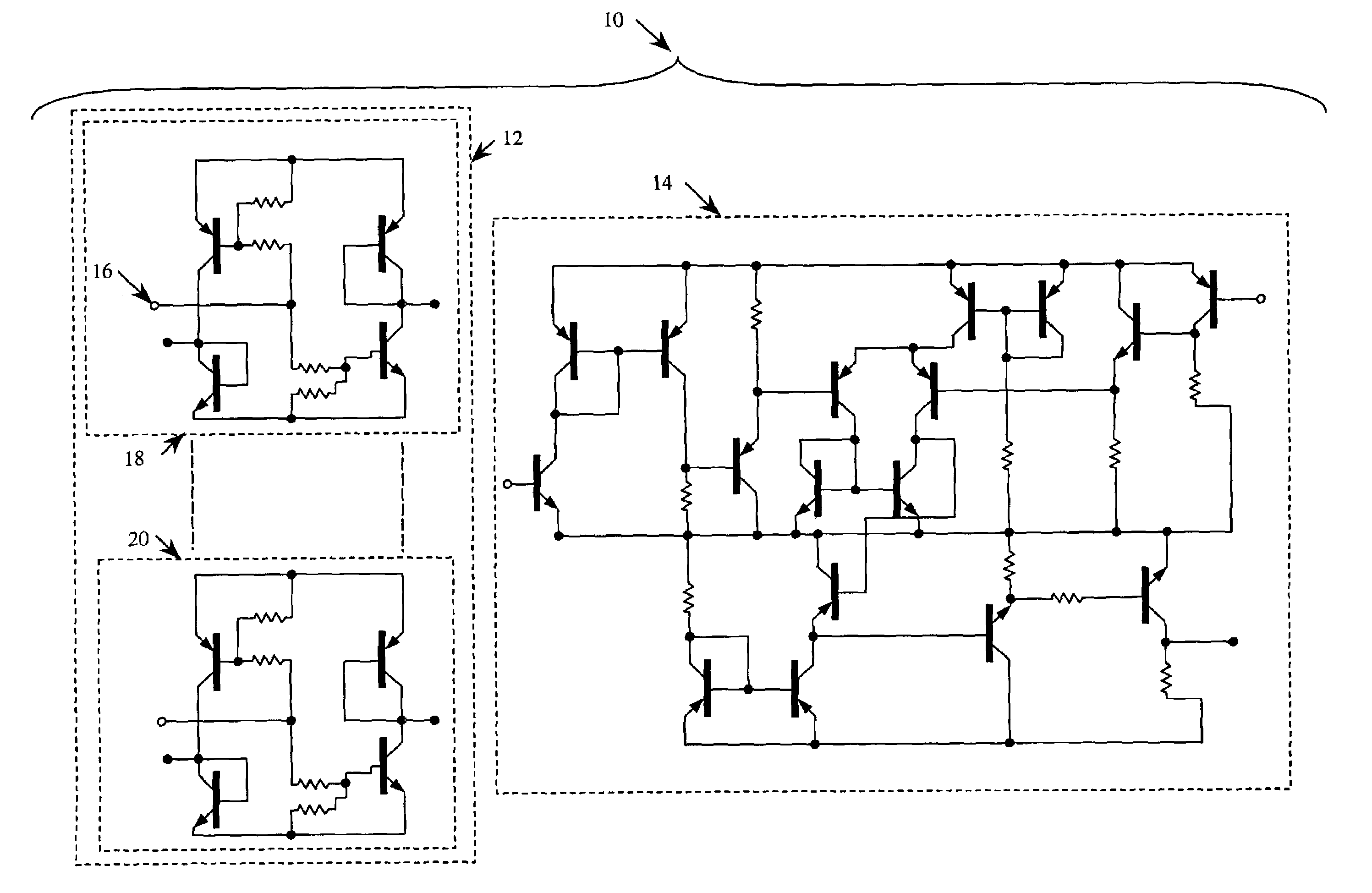
[0014]The present invention comprises a novel majority logic circuit to provide an indication of the binary state of the majority of the inputs. The output of the present invention is provided in the same number of clock cycles, regardless of the number of inputs.

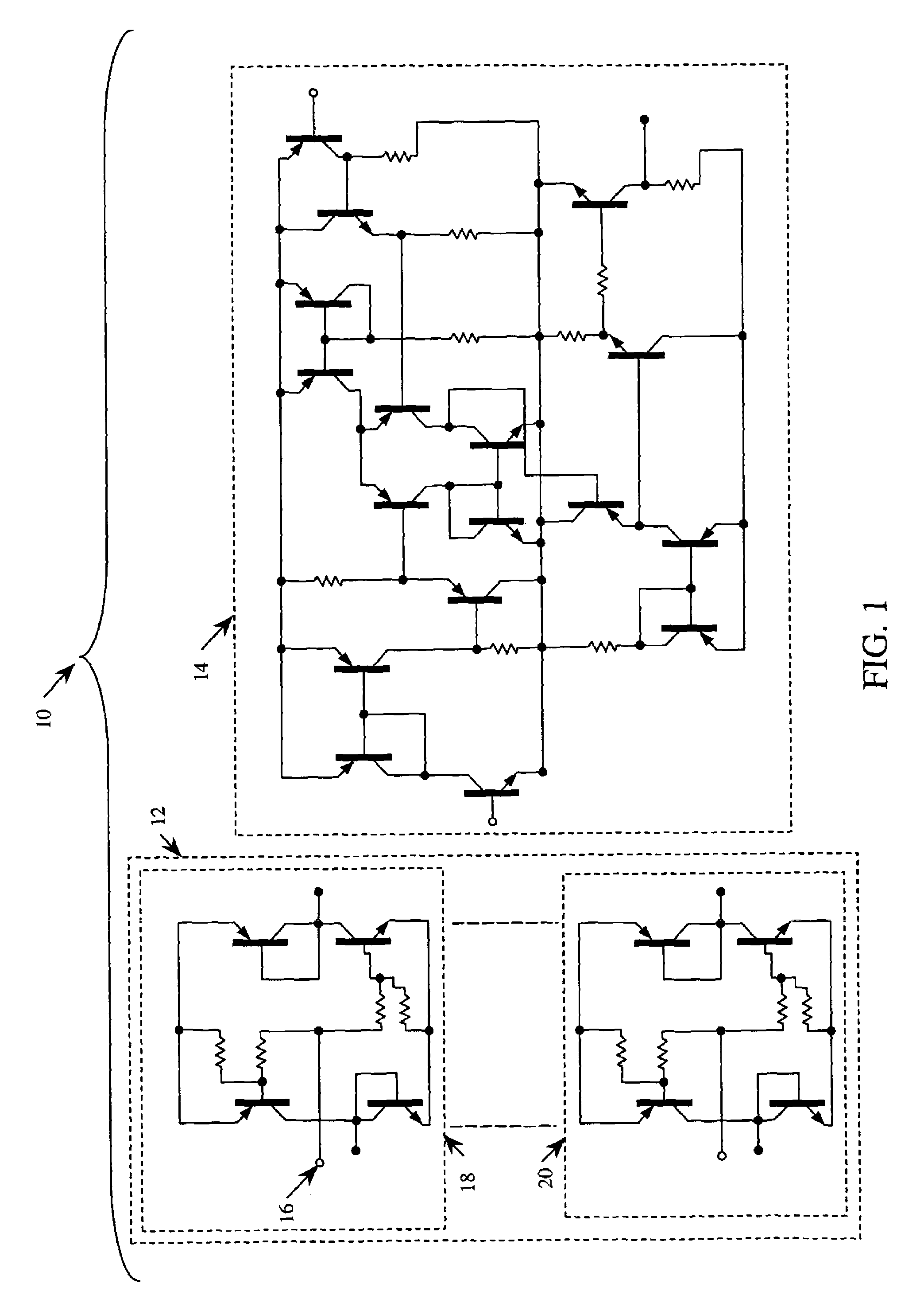
[0015]Referring to FIG. 1, a majority logic circuit 10 according to the present invention is shown. The majority logic circuit 10 has a plurality of current mirrors 12, and an amplifier 14. The number of the plurality of current mirrors 12 equals the number of inputs 16 to the majority logic circuit 10. In the preferred embodiment, the majority logic circuit 10 has an odd number of inputs 16. Only the first current mirror 18 and the Nth current mirror 20 are shown.

[0016]The majority logic circuit 10 employs a number of bipolar transistors, either of the NPN type or the PNP type. Each transistor has an emitter, a base, and a collector.

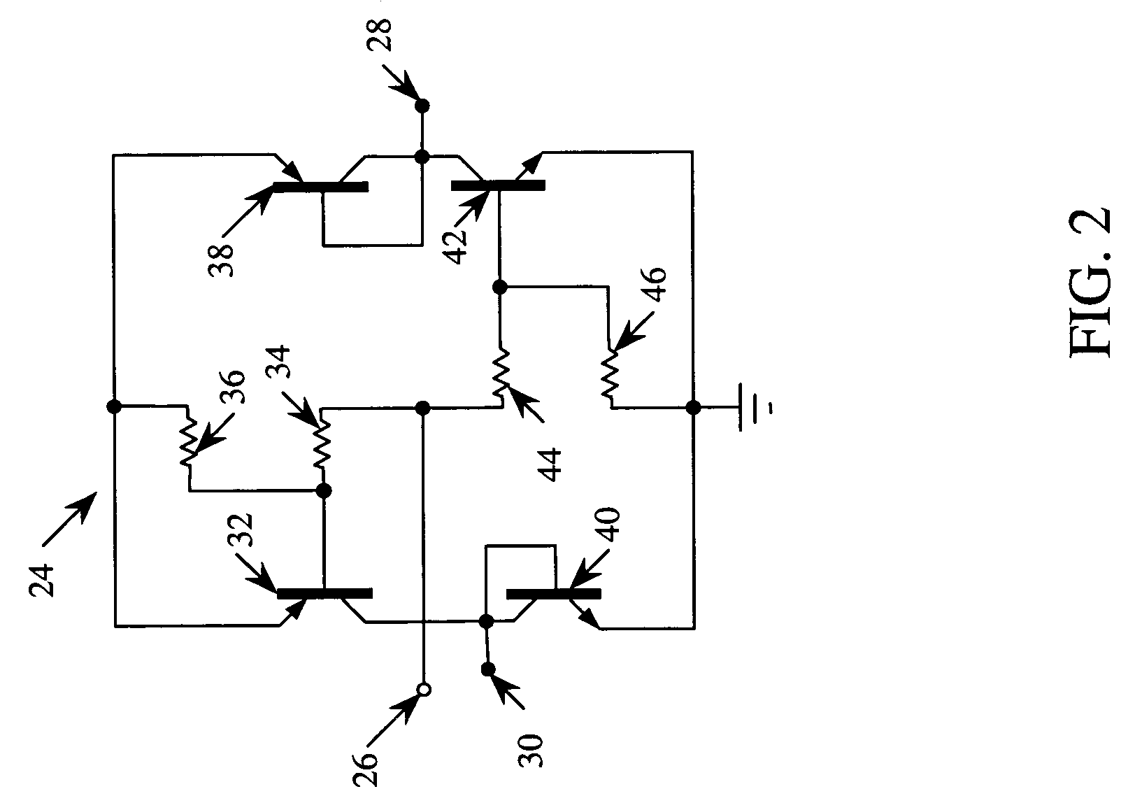
[0017]Each of the plurality of current mirrors 12 is identical, and only the first current ...


PUM


Abstract

A novel majority logic circuit is disclosed to determine whether the majority of the inputs are a one, within a constant number of clock cycles, regardless of the number of inputs. The majority logic circuit according to the present invention includes a plurality of current mirror stages and an amplifier stage. For each input, one current mirror stage is used, which outputs either a current source if the input is a one, or a current sink if the input is a zero. The current sources of all the input current mirror stages are connected in parallel to the current source input node of the amplifier stage. The current sinks of all the input current mirror stages are connected in parallel to the current sink input node of the amplifier stage. The amplifier is a differential type, which outputs either a positive voltage or a zero voltage depending upon the majority of the inputs.

Description

FIELD OF THE INVENTION[0001]The present invention relates, in general, to electronic digital logic circuitry, and, in particular to determining the value of a majority of the inputs.BACKGROUND OF THE INVENTION[0002]A majority logic circuit indicates whether a majority of binary inputs are equal to one. Prior art techniques accomplish this by either counting the number of inputs, or by using Boolean logic. Typically, an odd number of inputs are used to eliminate the possibility of having an equal number of ones and zeros.[0003]U.S. Pat. No. 4,091,293, entitled “MAJORITY DECISION LOGIC CIRCUIT,” discloses a method of detecting buffer overflow exploits by searching for pointer fingerprints. A pointer fingerprint is a portion of a pointer containing at least a portion of the return address. Preferably, the method searches for the return address of a jump function only in portions of the stack where jump functions are not expected. This method requires extensive use of processor resource...

Claims


Application Information

Patent Timeline
IPC IPC(8): H03K19/23
CPCH03K19/23
Inventor KUEHNEL, RICHARD JOHN
Owner NATIONAL SECURITY AGENCY
Why Eureka
Try Eureka