Servo loop for well bias voltage source

Active Publication Date: 2006-10-31
INTELLECTUAL VENTURES HOLDING 81 LLC
View PDF16 Cites 18 Cited by
  • Summary
  • Abstract
  • Description
  • Claims
  • Application Information

AI Technical Summary

Benefits of technology

[0011]Thus, a need exists for a system for controlling a charge pump t

Problems solved by technology

Although low operating voltages offer the potential for reduced power consumption, threshold voltage variations due to process an

Method used


Image

  • Servo loop for well bias voltage source
  • Servo loop for well bias voltage source
  • Servo loop for well bias voltage source

Examples


Embodiment Construction

[0023]In the following detailed description of the present invention, a feedback-controlled body-bias circuit, numerous specific details are set forth in order to provide a thorough understanding of the present invention. However, it will be obvious to one skilled in the art that the present invention may be practiced without these specific details. In other instances well known methods, procedures, components, and circuit elements have not been described in detail as not to unnecessarily obscure aspects of the present invention.

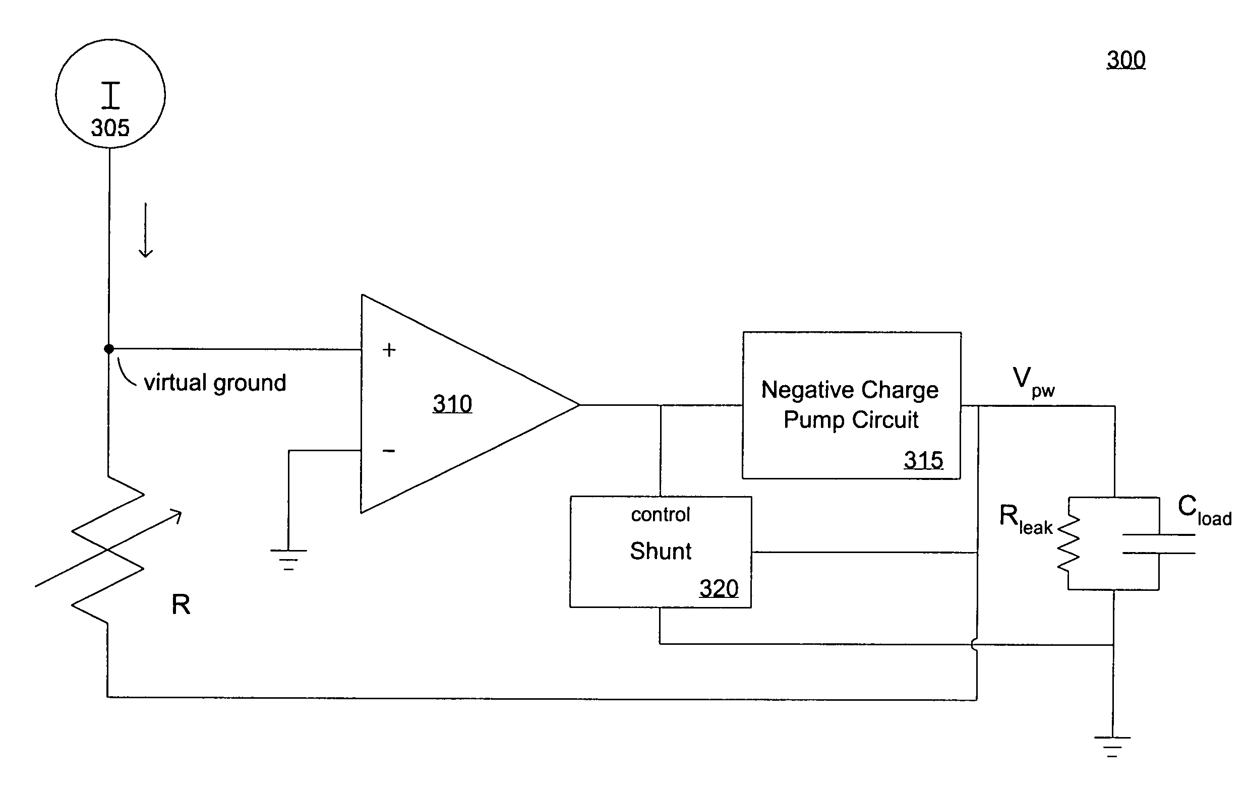
[0024]FIG. 2 shows a block diagram 200 of an embodiment of the present invention. A charge pump 210 has an output coupled to Cload that represents a substrate or well. Since body-bias is typically applied as a reverse bias to a p-n junction within a CMOS device, the load seen by the body-bias voltage source is generally a capacitive load; however, there is a certain amount of leakage current, represented by Rleak.

[0025]An output monitor 205 has a sense input...


PUM


Abstract

A servo loop for a charge pump including comparator. A variable resistor and comparator are in series and couple the output of the charge pump to an enable input. A current source/sink coupled to the variable resistor provide a first input voltage to the comparator, with the second input of the comparator being coupled to ground or Vdd. A shunt circuit in parallel with the load at the output of the charge pump is also coupled to the output of the comparator. The charge pump and shunt are alternately enabled and disabled by the comparator to maintain a body-bias supply voltage. The servo loop may be configured to provide body-bias for NFETs or PFETs.

Description

RELATED UNITED STATES PATENT APPLICATIONSThis Application is related to U.S. patent application Ser. No. 10 / 747,016 by Tien-Min Chen, et al., on Dec. 23, 2003, entitled “Feedback Controlled Body-Bias Voltage Source”, and assigned to the assignee of the present invention.[0001]This Application is related to U.S. patent application Ser. No. 10 / 746,539 by Tien-Min Chen and Robert Fu, filed on Dec. 23, 2003, entitled “A Precise Control Component for a Substrate Potential Regulation Circuit”, and assigned to the assignee of the present invention.[0002]This Application is related to U.S. patent application Ser. No. 10 / 747,022 by Tien-Min Chen, filed on Dec. 23, 2003, now U.S. Pat. No. 7,012,461 entitled “A Charge Stabilizing Component for a Substrate Potential Regulation Circuit”, and assigned to the assignee of the present invention.FIELD OF THE INVENTION[0003]Embodiments of the present invention relate to circuits for providing operational voltages in complementary metal-oxide semicondu...

Claims


Application Information

Patent Timeline
IPC IPC(8): G05F1/10
CPCG11C5/145H02M3/07H02M2003/071H02M3/071
Inventor CHEN, TIEN-MIN
Owner INTELLECTUAL VENTURES HOLDING 81 LLC
Why Eureka
Try Eureka