
Flash memory, program circuit and program method thereof

a flash memory and program circuit technology, applied in the field of flash memory program circuits, can solve the problems of requiring more time to program, unable to achieve the effect of rapid programming, and longer resistance-capacitance delay time of word lines, so as to reduce the complexity and cost of (charge pump) circuit design, and shorten the time for programming

Active Publication Date: 2008-05-29
MACRONIX INT CO LTD
View PDF5 Cites 20 Cited by
  • Summary
  • Abstract
  • Description
  • Claims
  • Application Information

AI Technical Summary

Benefits of technology

[0005]One aspect of this invention is to provide a flash memory. The program circuit of the flash memory utilizes a constant current to program the memory elements, which can reduce the complexity and cost of (charge pump) circuit design and shorten the time for programming.
[0006]One aspect of this invention is to provide a flash memory programming method, which utilizes a constant current and gate voltage to program the flash memory; hence, the specification requirements for an internal charge pump or external power source are lowered, and the threshold voltage after programming achieves higher concentration.
[0012]The present invention applies a constant current and constant gate voltage to program the flash memory, and judge the change of the threshold voltage by the drain voltage of the flash memory. Hence, the present invention can accurately modulate the threshold voltage of the flash memory after programming operation, and reduce the complexity of the program circuit and lower the specification requirements for the internal charge pump or external power. Additionally, the present invention can adjust the threshold voltage to the necessary value in one-time programming, which greatly shortens the programming time.

Problems solved by technology

However, the resistance-capacitance (RC) delay time of a word line is usually longer.
It would require more time to program and cannot achieve the effect of rapid programming.
Nevertheless, this method requires a gradual change in the drain voltage and a circuit for detecting current thereof.
A charge pump is required to supply stable voltage and a current-detecting circuit is required to detect the current conducted in the flash memory; the current-detecting circuit is more difficult to realize and the needed chip area is larger.
It is more difficult to control the threshold voltage after programming, which would decrease the accuracy of the read result in the flash memory.

Method used


Image

  • Flash memory, program circuit and program method thereof
  • Flash memory, program circuit and program method thereof
  • Flash memory, program circuit and program method thereof

Examples


Embodiment Construction

[0020]Reference will now be made in detail to the present preferred embodiments of the invention, examples of which are illustrated in the accompanying drawings. Wherever possible, the same reference numbers are used in the drawings and the description to refer to the same or like parts.

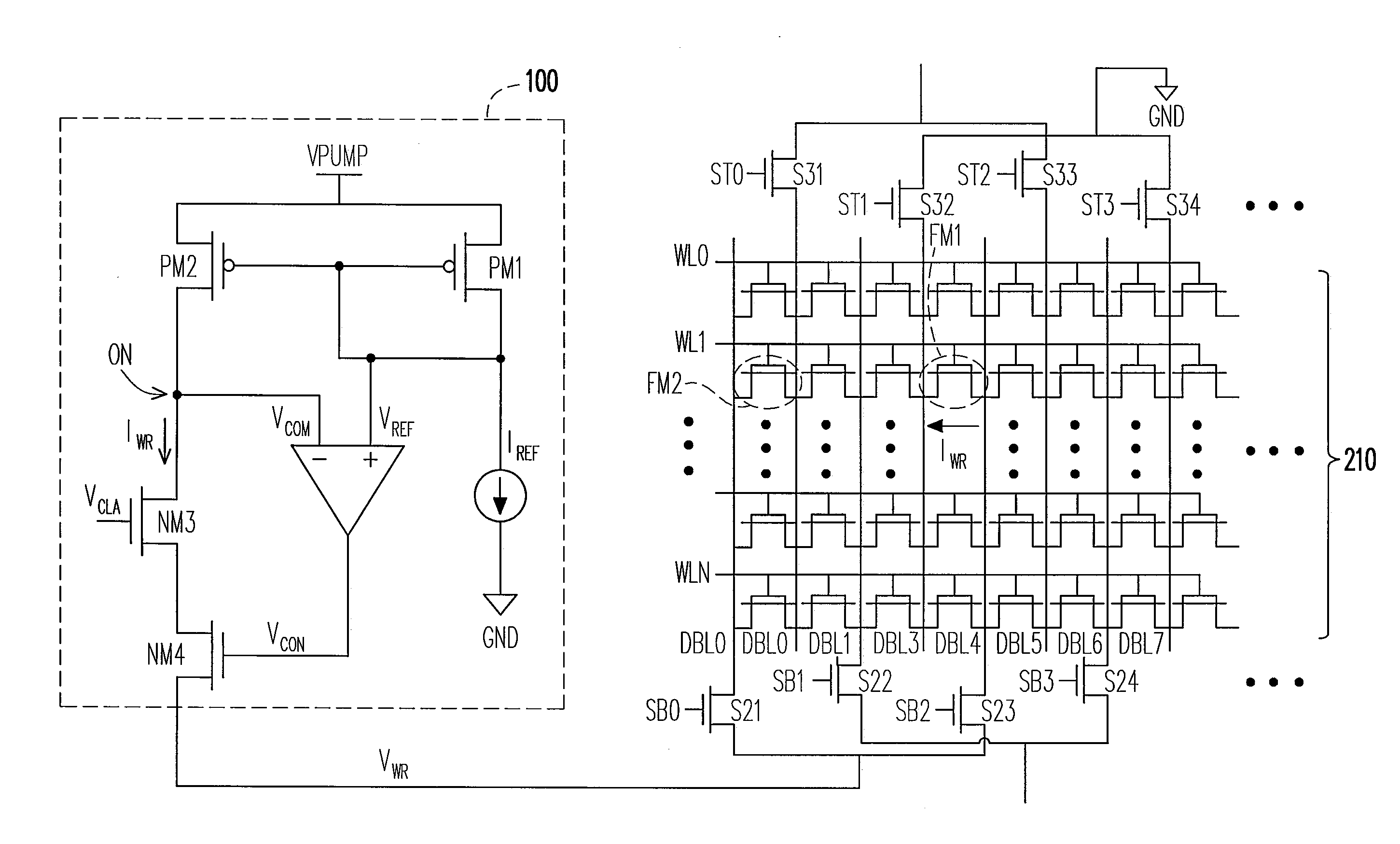
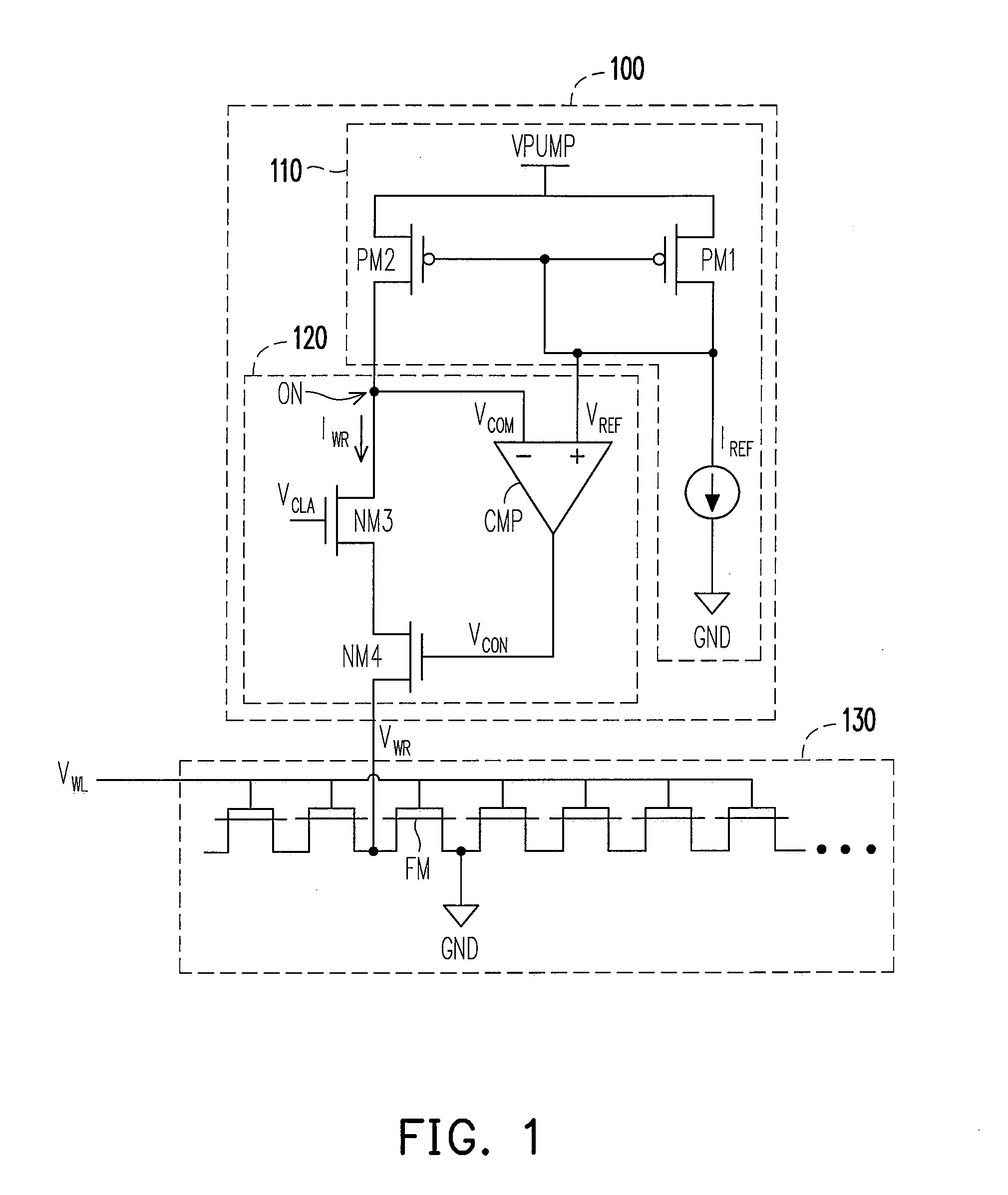
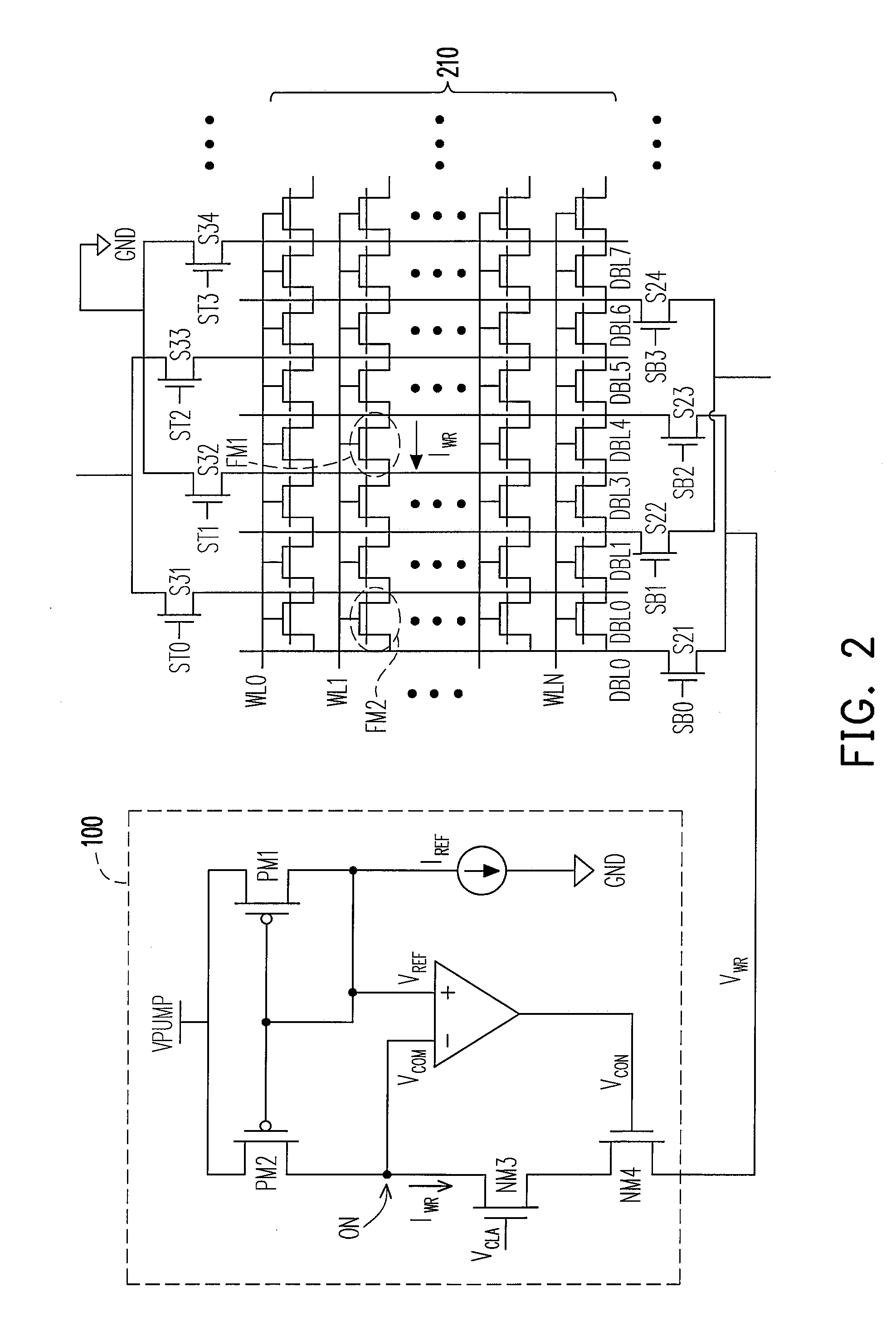
[0021]FIG. 1 is a diagram showing a program circuit for a flash memory according to one preferred embodiment of the present invention. Program circuit 100 includes a program unit 110 and a detecting unit 120, wherein the program Unit 100 is applied to program the memory element FM of a memory unit 130. In this embodiment, the memory element FM is a floating memory, i.e. one kind of flash memory. The control gate of the memory element FM connects a word line, and the word line can impose a word line voltage VWL on the control terminal (control gate) of the memory element FM.

[0022]The program circuit 100 is coupled to the program terminal (drain) of the memory element FM, and the source of the memory e...


PUM


Abstract

A program circuit and method for a flash memory is provided. This invention utilizes a constant current to program the flash memory and modulate the threshold voltage of the flash memory. While a program circuit programming the flash memory, the present invention determines whether the threshold voltage reaches the anticipated value according to the variation of the drain voltage of the flash memory. Hence, the present invention can accurately modulate the threshold voltage of the programmed flash memory and shorten the programming time.

Description

BACKGROUND OF THE INVENTION[0001]1. Field of the Invention[0002]The present invention relates to a program circuit for a flash memory. More particularly, the invention relates to a program circuit and a program method for the flash memory with a floating gate.[0003]2. Description of Related Art[0004]A flash memory has the feature of being light and non-volatile; therefore, it is commonly applied in portable devices, such as storage devices of mobile phones, MP3 players and digital cameras. Presently, the most extensively applied memory element in the flash memory is floating gate memory, whose structure is similar to that of a metal oxide semiconductor transistor, MOS, with a floating gate. In traditional technology, the way to program a floating memory usually is to set a high voltage potential between its control gate and drain, so as to trap electrons in the floating gate. The threshold voltage of the floating gate memory then fluctuates with the amount of electrons trapped in th...

Claims


Application Information

Patent Timeline
IPC IPC(8): G11C16/06
CPCG11C16/10
Inventor HSU, JER-HAO
Owner MACRONIX INT CO LTD
Learn More