Computer input device with multi-purpose light guide

Inactive Publication Date: 2006-10-31
MICROSOFT TECH LICENSING LLC
View PDF9 Cites 16 Cited by
  • Summary
  • Abstract
  • Description
  • Claims
  • Application Information

AI Technical Summary

Problems solved by technology

Although simple in some respects, this configuration can add additional steps to an assembly process, and can also be a potential source of errors because of improper alignment.
Moreover, many commercially available LEDs are not optimized for direct illumination of a near-field object (such as a target area of a tracking surface), resulting in less-than-desirable illumination patterns.
For example, a conventional mouse may be difficult to locate in low light conditions, potentially making mouse (and computer) use less efficient.
Although the mouse is usually within reach of the user, it may be difficult to locate and orient the mouse if the user cannot easily see it.
An ON / OFF indicator light located on the CPU housing might thus be difficult to see.
Two LEDs draw significant power and can reduce battery life in wireless or other battery operated components (e.g., a wired mouse connected to a battery powered laptop computer).
This increases assembly steps and manufacturing costs, as does the need to buy two LEDs for each device.

Method used


Image

  • Computer input device with multi-purpose light guide
  • Computer input device with multi-purpose light guide
  • Computer input device with multi-purpose light guide

Examples


Embodiment Construction

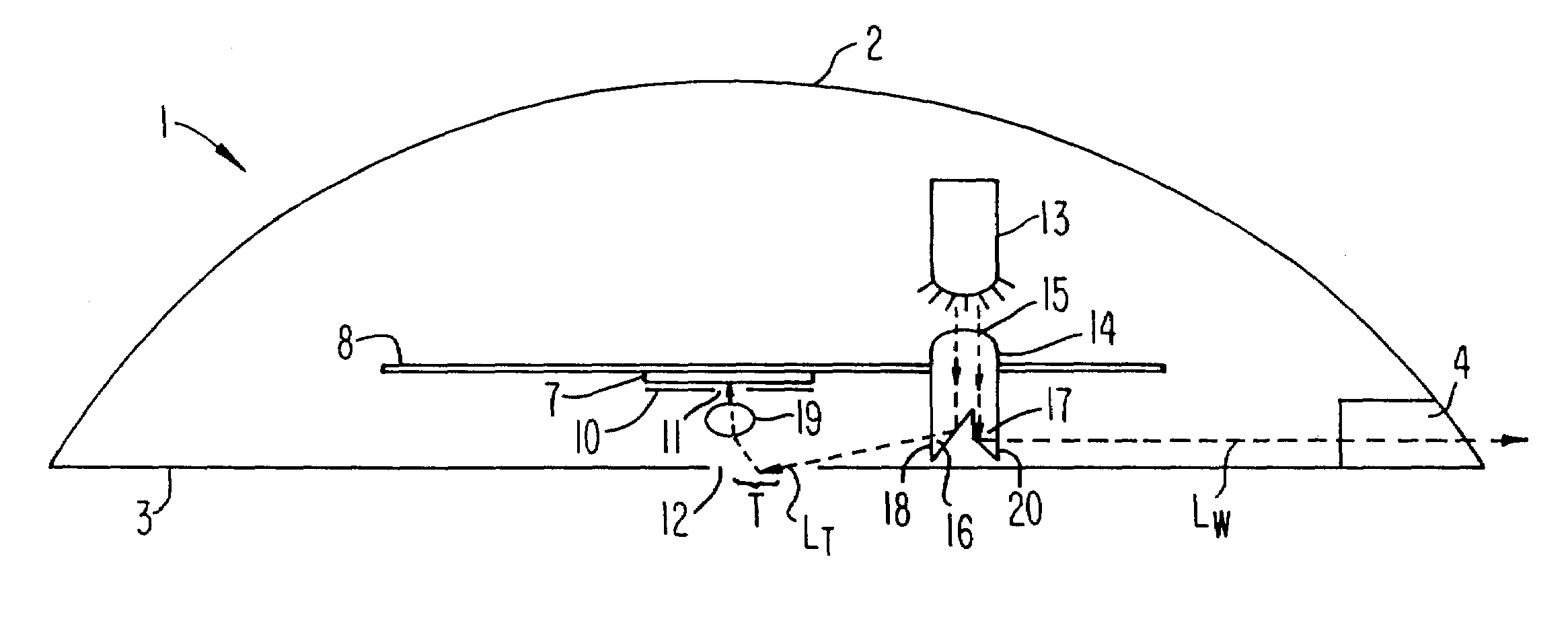
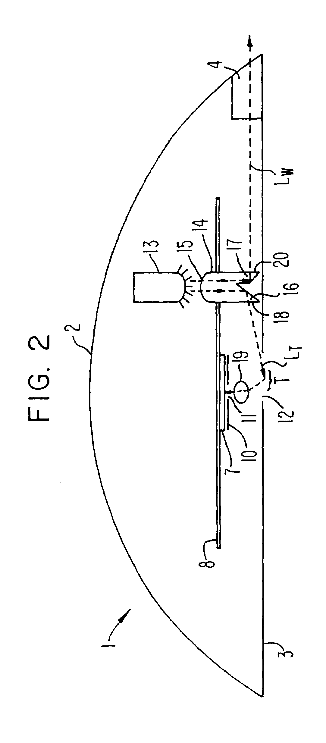
[0020]The invention is described using an optically-tracking computer mouse as an example of a device into which the invention may be incorporated. However, the invention is not limited to computer mice.

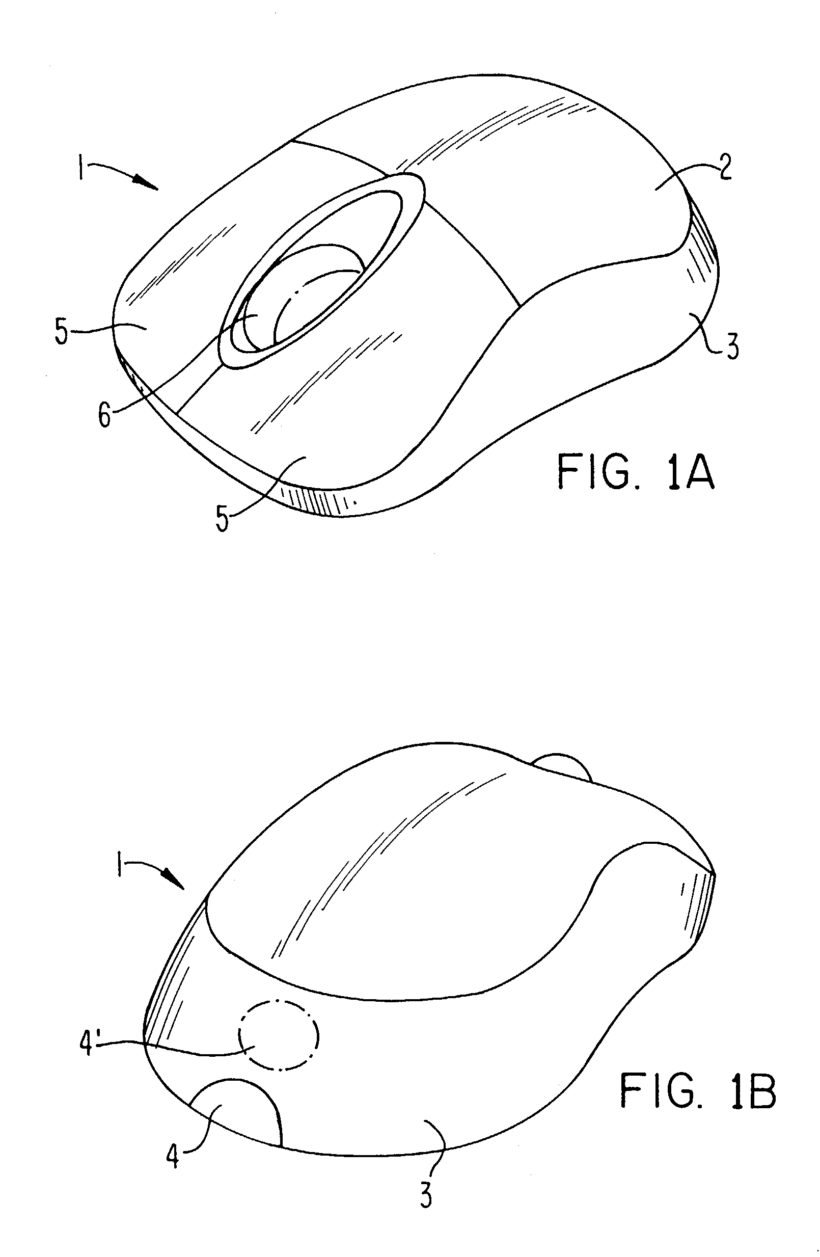
[0021]FIGS. 1A and 1B are perspective views of a mouse 1. Mouse 1 includes an upper housing 2 and a lower housing 3. Lower housing 3 has a substantially flat bottom surface that is arranged to rest on a supporting surface such as a desk or table top. Upper housing 2 is shaped to comfortably interface with and support a human hand. Mouse 1 further includes an externally-visible light window 4. Light window 4 may be transparent or translucent, and may also be color tinted. Window 4 is arranged so that light from an internal light source (as described more fully below) is visible to a mouse user when the lower housing 3 of mouse 1 rests upon a supporting surface. Window 4 could be located elsewhere on mouse 1; an example of a possible alternate location includes, but is not limited to, ...


PUM


Abstract

A computer input device includes a light guide that illuminates a target area for imaging so as to permit tracking relative motion of a surface. The light guide also directs light to a window that is externally visible to a user of the device when the device rests upon a supporting surface. In one form, the light guide includes an entrance surface that receives light from a light source, together with two separated channels. The light guide directs a portion of the light incident upon the entrance surface through a first channel to the target area. The light guide further directs a portion of the incident light through a second channel so as to illuminate the window.

Description

FIELD OF THE INVENTION[0001]This invention relates generally to optical components usable in optically-tracking pointing and input devices such as computer mice. More particularly, this invention provides a light guide for illuminating a target area and for also illuminating a portion of an input device that is visible to a user.BACKGROUND OF THE INVENTION[0002]Computer input and other pointing devices, such as electronic mice, convert physical movement into movement of a cursor or other image across a computer screen. Previously, many such devices utilized mechanically driven encoder wheels and other moving components to detect direction and magnitude of motion, and to then convert that information into data for communication to a computer or other device. Optical surface tracking offers an improved method of motion detection. Instead of encoder wheels rotated by a ball rolling across a surface, an array of photo-sensitive elements generates an image of a desktop (or other supporti...

Claims


Application Information

Patent Timeline
IPC IPC(8): G09G5/08
CPCG06F3/0317G06F3/03543
Inventor BOHN, DAVID D.
Owner MICROSOFT TECH LICENSING LLC
Why Eureka
Try Eureka