On-chip spectral filtering using CCD array for imaging and spectroscopy

a spectral filtering and array technology, applied in the field of imaging and spectral analysis, can solve the problems of slow approach, inability to easily change, and limited number of separate fluorescence emission and detection channels

Active Publication Date: 2006-10-31
LI-COR BIOTECH LLC
View PDF7 Cites 94 Cited by
  • Summary
  • Abstract
  • Description
  • Claims
  • Application Information

AI Technical Summary

Problems solved by technology

These techniques differ in their detection capability, speed, and cost, but a common challenge to all fluorescence imaging techniques is the separation of the light used to excite the targeted fluorophores from the emitted fluorescence light.
This approach is characterized by limitations as to the number of separate fluorescence emissions and the number of detection channels that can be used in the same system in parallel.
Significantly, this approach requires fixed band-pass filters and thus cannot be easily changed to adapt to variations in the wavelength(s) of the fluorescence light being detected.
Unless the technology used in tuning the filter is fast, this approach tends to be slow, particularly if higher spectral resolution is needed.
These filters are fast, but they are expensive and suffer from high optical insertion loss.
Furthermore, since they require sequential detection band-by-band, they can result in a much slower process than the filter itself is capable of.
Spectrometers also are expensive and have an even higher insertion loss than the LC or AOTF filters.
However, because a significant amount of data is read and stored for each point or line, the speed of operation and the storage capacity required can become overwhelming, even for a small area scan.

Method used


Image

  • On-chip spectral filtering using CCD array for imaging and spectroscopy
  • On-chip spectral filtering using CCD array for imaging and spectroscopy
  • On-chip spectral filtering using CCD array for imaging and spectroscopy

Examples


Embodiment Construction

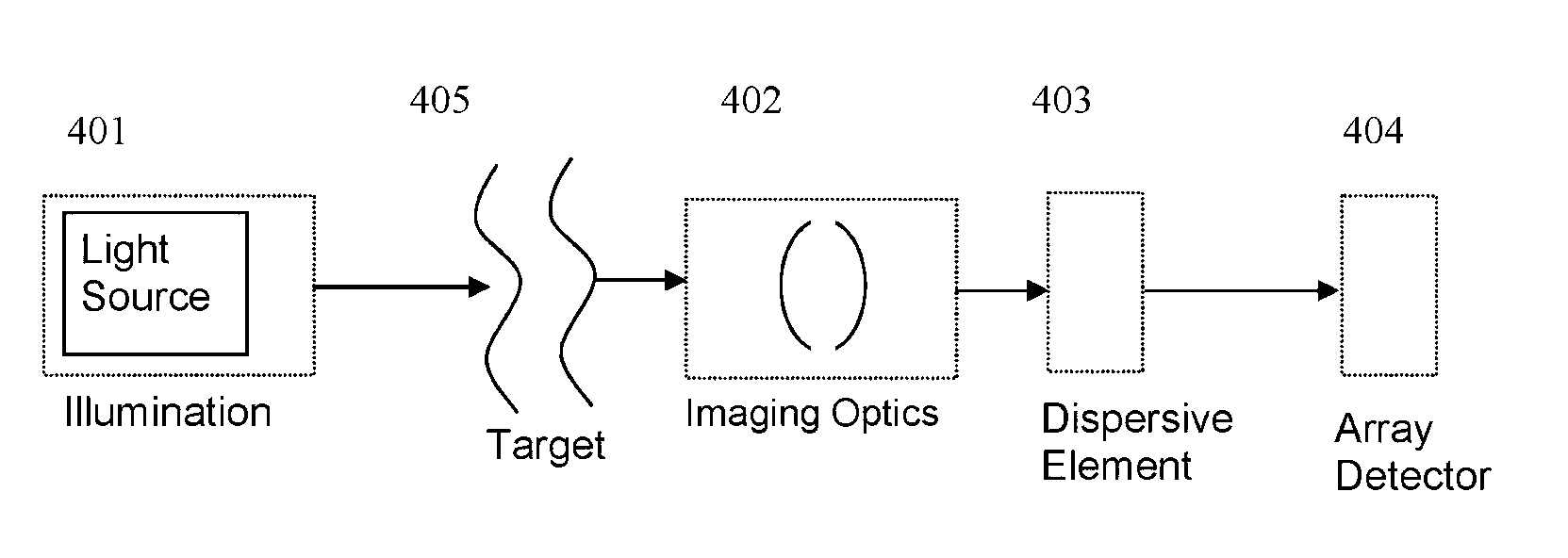
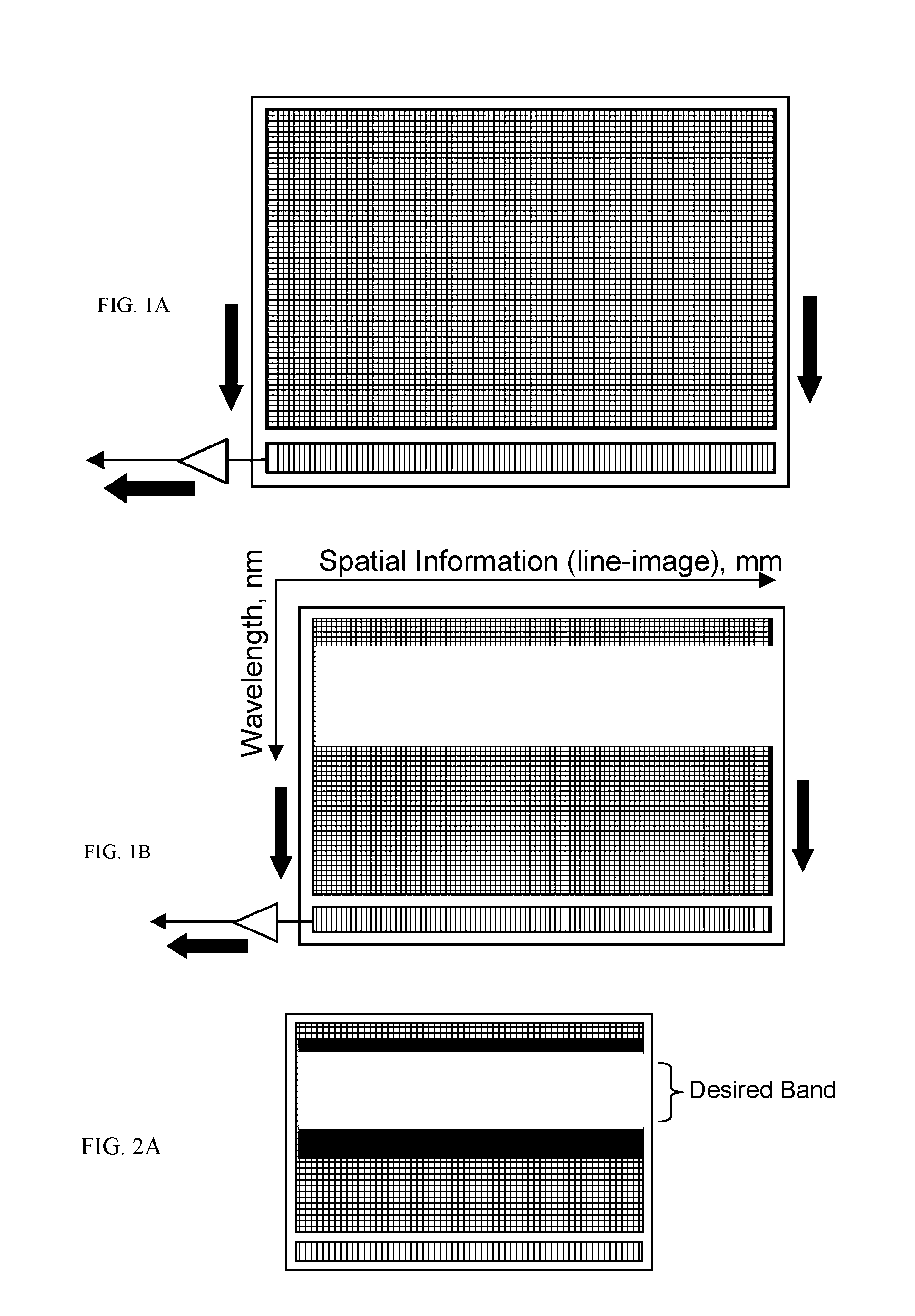
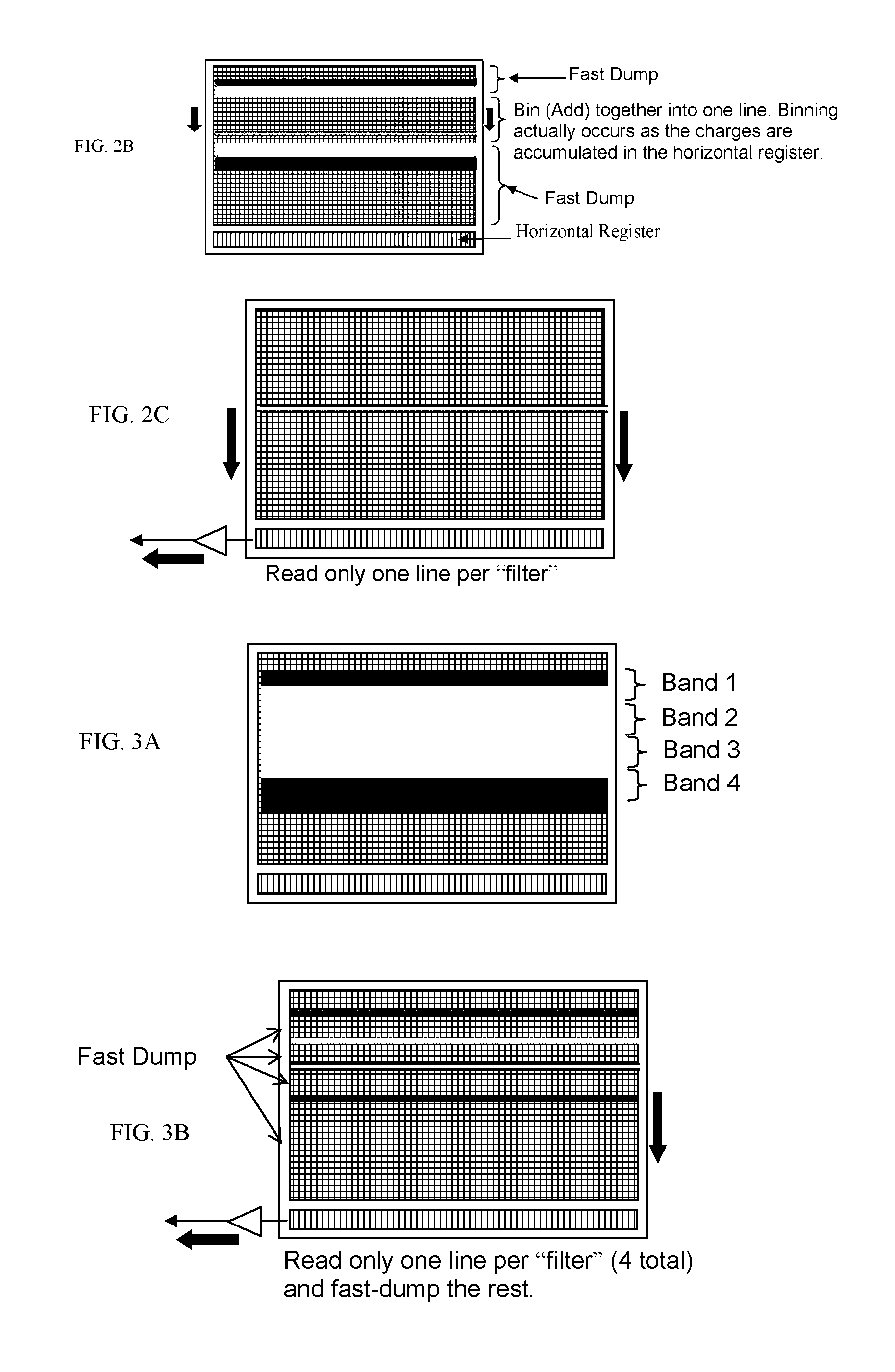
[0031]According to one embodiment of the invention, a CCD (charge-coupled device) array detector is used for hyperspectral imaging and filtering. A CCD array consists of a matrix of pixels that are sensitive to light. In response to the impingement of light photons, individual pixels in the array generate a charge of electrons, the amount of which varies in proportion to the magnitude of light photons interacting with the pixel areas and proportional to exposure time. The resulting electrical signals are read out of the array and are interpreted to correspond to the amount of light that generated the electrical charges in the pixel layers. The most common CCD architectures used in the instrumentation industry today are Full-Frame, Frame Transfer, and Interline (progressive) Transfer. In the former two, the pixels are typically constituted by photodiodes and the generated charges from the pixels of the entire array are read out directly or transferred simultaneously to another storag...


PUM


Abstract

A spectral filtering apparatus and method is presented, which enables the functions of hyperspectral imaging to be performed with increased speed, simplicity, and performance that are required for commercial products. The apparatus includes a photosensitive array having a plurality of photosensitive elements such that different subsections of photosensitive elements of the array receive light of a different wavelength range of a characteristic spectrum of a target, and output electronics combines signals of at least two photosensitive elements in a subsection of the array and outputs the combined signal as a measure of the optical energy within a bandwidth of interest of the characteristic spectrum.

Description

FIELD OF THE INVENTION[0001]The present invention relates generally to imaging and spectral analysis, and more particularly relates to apparatus and methods for imaging, data acquisition, filtering and processing.BACKGROUND OF THE INVENTION[0002]Various imaging, scanning, and detection techniques for detecting and quantifying fluorescent labels are known in the art. These techniques differ in their detection capability, speed, and cost, but a common challenge to all fluorescence imaging techniques is the separation of the light used to excite the targeted fluorophores from the emitted fluorescence light. One common method uses a combination of dichroic filters / beamsplitters and band-pass filters that isolate the fluorescence light for detection. This approach is characterized by limitations as to the number of separate fluorescence emissions and the number of detection channels that can be used in the same system in parallel. Significantly, this approach requires fixed band-pass fil...

Claims


Application Information

Patent Timeline
Patent Type & Authority Patents(United States)
IPC IPC(8): G01J3/44
CPCG01J3/2803G01J3/4406
Inventor BOUZID, AHMEDFRANZEN, DAVID L.LESIAK, CHRISTOPHER
Owner LI-COR BIOTECH LLC
Why Eureka
Try Eureka