Micromirror unit with torsion connector having nonconstant width

a micromirror unit and connector technology, applied in the field of micromirrors, can solve the problems of warping of the mirror member, affecting the operation of the micromirror unit, and the strength of the restoring force of the torsion bar tends to exceed the strength of the inter-electrode electrostatic force, so as to achieve excellent stability against undesired swiveling and reduce the restoring force

Inactive Publication Date: 2006-10-31
DRNC HLDG INC
View PDF16 Cites 7 Cited by
  • Summary
  • Abstract
  • Description
  • Claims
  • Application Information

AI Technical Summary

Benefits of technology

[0014]The present invention has been proposed under the circumstances described above. It is, therefore, an object of the present invention to provide a micromirror unit which does not suffer from the above-noted problems. Specifically, an object of the present invention is to provide a micromirror unit which is provided with torsion bars of reduced restoring force and still can exert excellent stability against undesired swiveling.

Problems solved by technology

According to the above-mentioned surface micro-machining technique, however, the thickness of the resulting mirror member is rendered very small, so that the mirror member is liable to warp.
This is rather large size, and therefore the restoring force of the torsion bars tends to exceed the inter-electrode electrostatic force in strength.
When such an unwanted swivel occurs, it is difficult or even impossible to precisely control the operation of the micromirror unit.

Method used


Image

  • Micromirror unit with torsion connector having nonconstant width
  • Micromirror unit with torsion connector having nonconstant width
  • Micromirror unit with torsion connector having nonconstant width

Examples


first embodiment

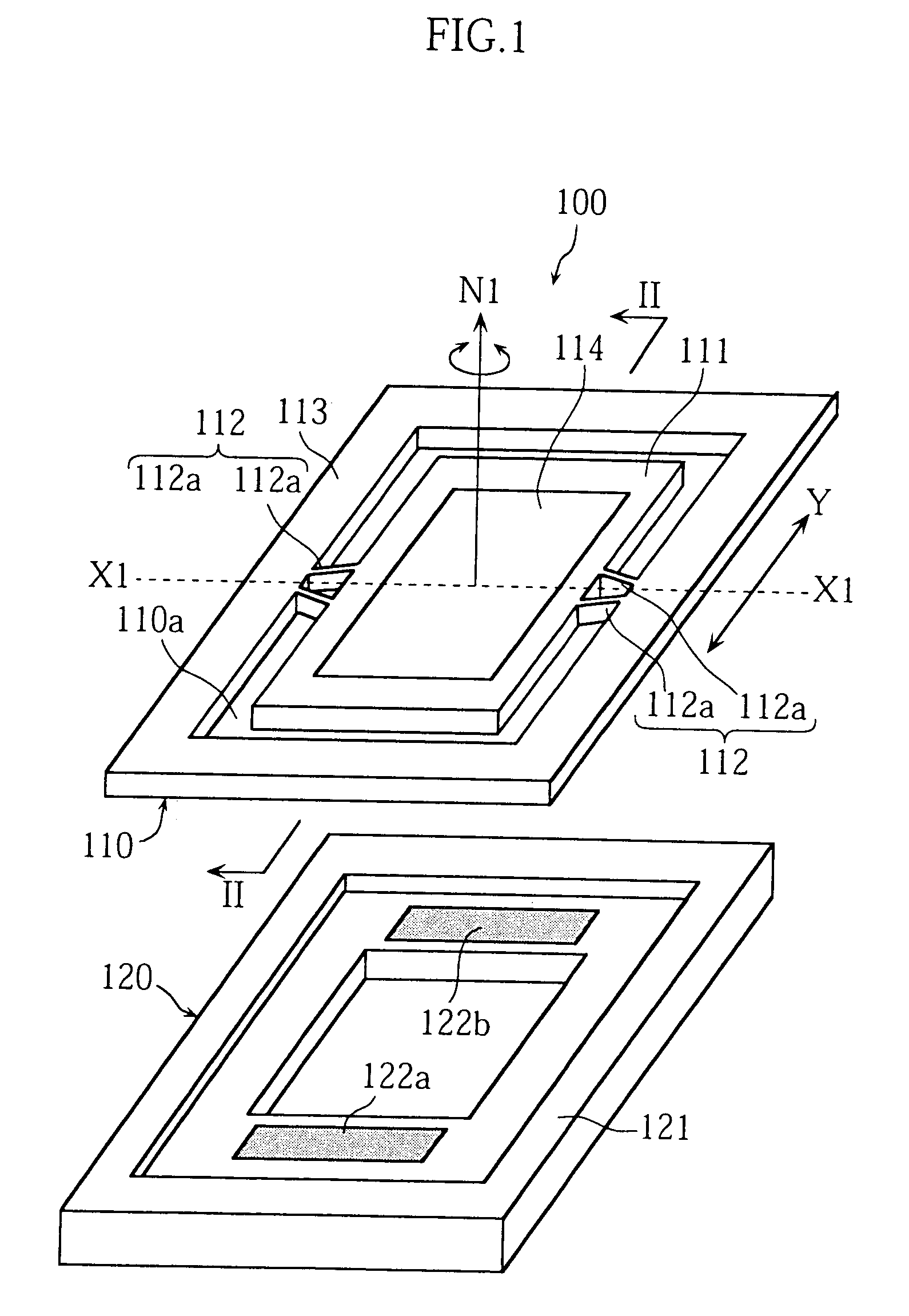
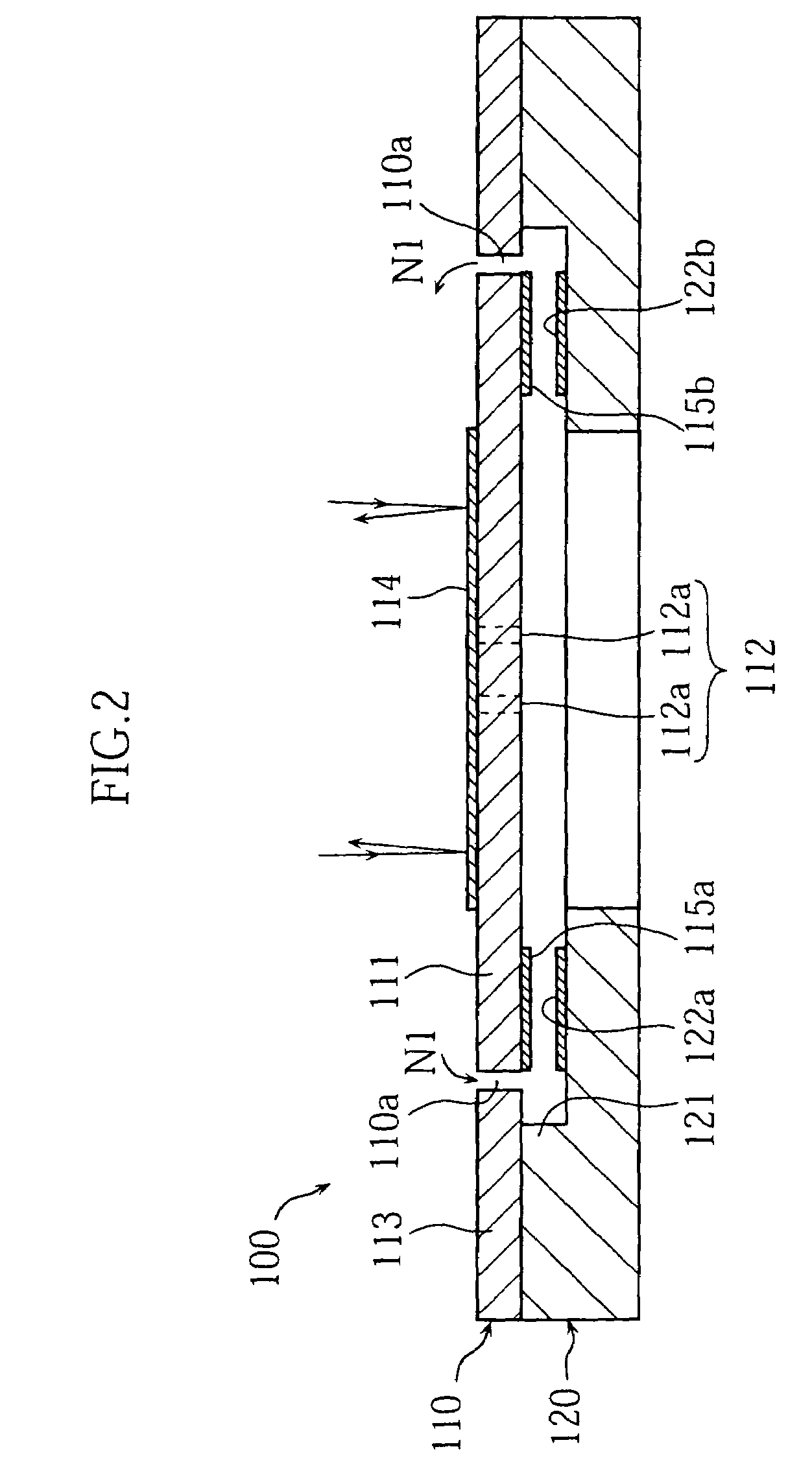
[0048]FIGS. 1 and 2 show a micromirror unit 100 according to the present invention. The illustrated unit 100 is a “static driving type” device, and includes two superposed substrates, i.e., a mirror substrate 110 and a base substrate 120.

[0049]As shown in FIG. 1, the mirror substrate 110 includes a mirror forming base 111, a frame 113 around the base 111, and a pair of torsion connectors 112 connecting the base 111 to the frame 113. The mirror substrate 110 may be made of a conductive silicon material doped with n-type impurity (such as phosphorous or arsenic) or p-type impurity (e.g. boron). The mirror substrate 110 may be fabricated by a bulk micro-machining technique. Specifically, first a plate of conductive silicon substrate is prepared. Then, for forming several openings 110a (see the figure), portions of the silicon plate that correspond to the mirror forming base 111, the frame 113 and the torsion connectors 112 are covered by an etching mask. Finally, the masked silicon pla...

second embodiment

[0057]Reference is now made to FIGS. 3A–3B and 4A–4C illustrating a micromirror unit 200 according to the present invention. The upper view of the unit 200 is shown in FIG. 3A, while the bottom view is shown in FIG. 3B. FIGS. 4A, 4B and 4C are sectional views taken along lines A—A, B—B and C—C in FIG. 3, respectively.

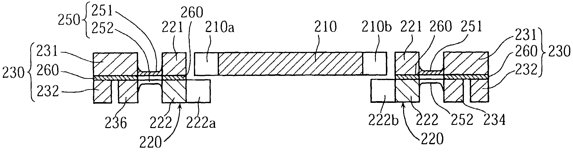
[0058]As shown in FIGS. 3A and 3B, the micromirror unit 200 of the second embodiment includes a mirror forming base 210, an inner frame 220 surrounding the base 210, an outer frame 230 surrounding the inner frame 220, a pair of first torsion connectors 240 connecting the mirror forming base 210 to the inner frame 220, and a pair of second torsion connectors 250 connecting the inner frame 220 to the outer frame 230. The first torsion connectors 240 have a first rotation axis X2 about which the mirror forming base 210 is rotated with respect to the inner frame 220. The second torsion connectors 250 have a second rotation axis X3 about which the inner frame 220 is rotated ...


PUM

PropertyMeasurementUnit
lengthaaaaaaaaaa
thicknessaaaaaaaaaa
widthaaaaaaaaaa

Abstract

A micromirror unit is provided which includes a frame, a mirror forming base upon which a mirror surface is formed, and a torsion connector which includes a first end connected to the mirror forming base and a second end connected to the frame. The torsion connector defines a rotation axis about which the mirror forming base is rotated relative to the frame. The torsion connector has a width measured in a direction which is parallel to the mirror surface and perpendicular to the rotation axis. The width of the torsion connector is relatively great at the first end. The width becomes gradually smaller from the first end toward the second end.

Description

CROSS-REFERENCE TO RELATED APPLICATION[0001]This application is a continuation of co-pending application Ser. No. 09 / 984,814, filed on Oct. 31, 2001, the entire contents and disclosure of which are entirely incorporated herein by reference.BACKGROUND OF THE INVENTION[0002]1. Field of the Invention[0003]The present invention relates to a micromirror unit used in optical apparatus for the purposes of changing the direction of light. In particular, it relates to a micromirror unit of the type which is advantageously incorporated in an optical disk apparatus (for writing to or reading data from an optical disk), an optical switching apparatus (for selectively connecting one optical fiber to another to provide a light passage), etc.[0004]2. Description of the Related Art[0005]A micromirror unit is provided with a reflective mirror member which is pivotable for changing the direction of reflected light. A popular technique for actuating the mirror member is to utilize electrostatic force....

Claims


Application Information

Patent Timeline
Patent Type & Authority Patents(United States)
IPC IPC(8): G02B26/08G11B7/135B81B3/00B81C1/00G11B7/09
CPCG02B26/0841G02B26/085Y10S359/904B81B3/00B81C1/00G02B26/08G11B7/1362
Inventor TSUBOI, OSAMUUEDA, SATOSHIMIZUNO, YOSHIHIROSAWAKI, IPPEIOKUDA, HISAO
Owner DRNC HLDG INC
Why Eureka
Try Eureka