Color image forming device and color deviation detection device for the same

a detection device and color image technology, applied in the direction of instruments, electrographic process devices, printing, etc., can solve the problems of increasing the fluctuation of width, reducing increasing the difficulty of mark pattern recognition, so as to improve the accuracy of color deviation correction, improve the reliability of color deviation detection, and reduce the error

Inactive Publication Date: 2006-10-31
RICOH KK
View PDF8 Cites 39 Cited by
  • Summary
  • Abstract
  • Description
  • Claims
  • Application Information

AI Technical Summary

Benefits of technology

[0016]It is an object of the present invention to provide a color deviation detection method, color deviation detection device, color image forming device, color deviation detection and correction method and color deviation detection and correction device which can improve the reliability of color deviation detection by actually taking into account the numerous causes of fluctuation, and considering and setting pattern dispositions in a state close to the fluctuations on the transfer medium in which these fluctuations occur, and which can improve the precision of color deviation correction by greatly reducing the error caused by the arrangement of the marks in mark patterns.
[0017]It is also an object of the present invention to provide a color deviation detection method, color deviation detection device, color image forming device, color deviation detection and correction method and color deviation detection and correction device which can shorten the time required for color deviation correction.
[0018]It is also an object of the present invention to provide a color deviation detection method, color deviation detection device, color image forming device, color deviation detection and correction method and color deviation detection and correction device which can detect the positions of the respective marks by means of relatively simple processing.

Problems solved by technology

High-frequency noise of the detection signals of the optical sensors can be suppressed by passing the detection signals of the optical sensors through a low-pass filter; however, if the cut-off frequency is shifted toward a lower region in order to strengthen this suppression, the L pulse width corresponding to the mark width of the binary signals from the comparator shows an increased fluctuation in width, so that mark pattern recognition, and especially specification of the positions of the respective marks, becomes difficult.
These problems become more severe with increasing contamination and scratching of the transfer belt, so that even if the useful life of the transfer application of the transfer belt is long, mark pattern detection for the purpose of color adjustment soon becomes impossible.
In this case, however, the amount of data that is handled is greatly increased so that a large memory capacity is required; in addition, the pattern identification processing is complicated, and requires a long processing time.
Specifically, the reliability of the measurements of the amount of deviation is low.
Furthermore, in the case of fluctuation components in products in which the circumferential length is longer than the total length of the plurality of mark sets, i.e., the pattern group length, measurements of the amount of deviation cannot be accurately performed using conventional pattern dispositions, so that correction that is conversely erroneous is commonly performed.
Furthermore, the work of replacing the photosensitive bodies or developing devices is itself a cause of fluctuation in the color deviation, and color deviation caused by slight differences in the part precision before and after such replacement also occurs.
Furthermore, in the prior art, accurate measurements of the amount of deviation cannot be performed in the case of fluctuation components of products with a circumferential length that is longer than the pattern group length, so that there is on the contrary a possibility that an erroneous correction amount will be calculated.
Naturally, this has contributed greatly to the cost involved, so that such parts are among the most expensive parts used in image forming devices.

Method used


Image

  • Color image forming device and color deviation detection device for the same
  • Color image forming device and color deviation detection device for the same
  • Color image forming device and color deviation detection device for the same

Examples


Embodiment Construction

[0067]The present invention will be described in detail below.

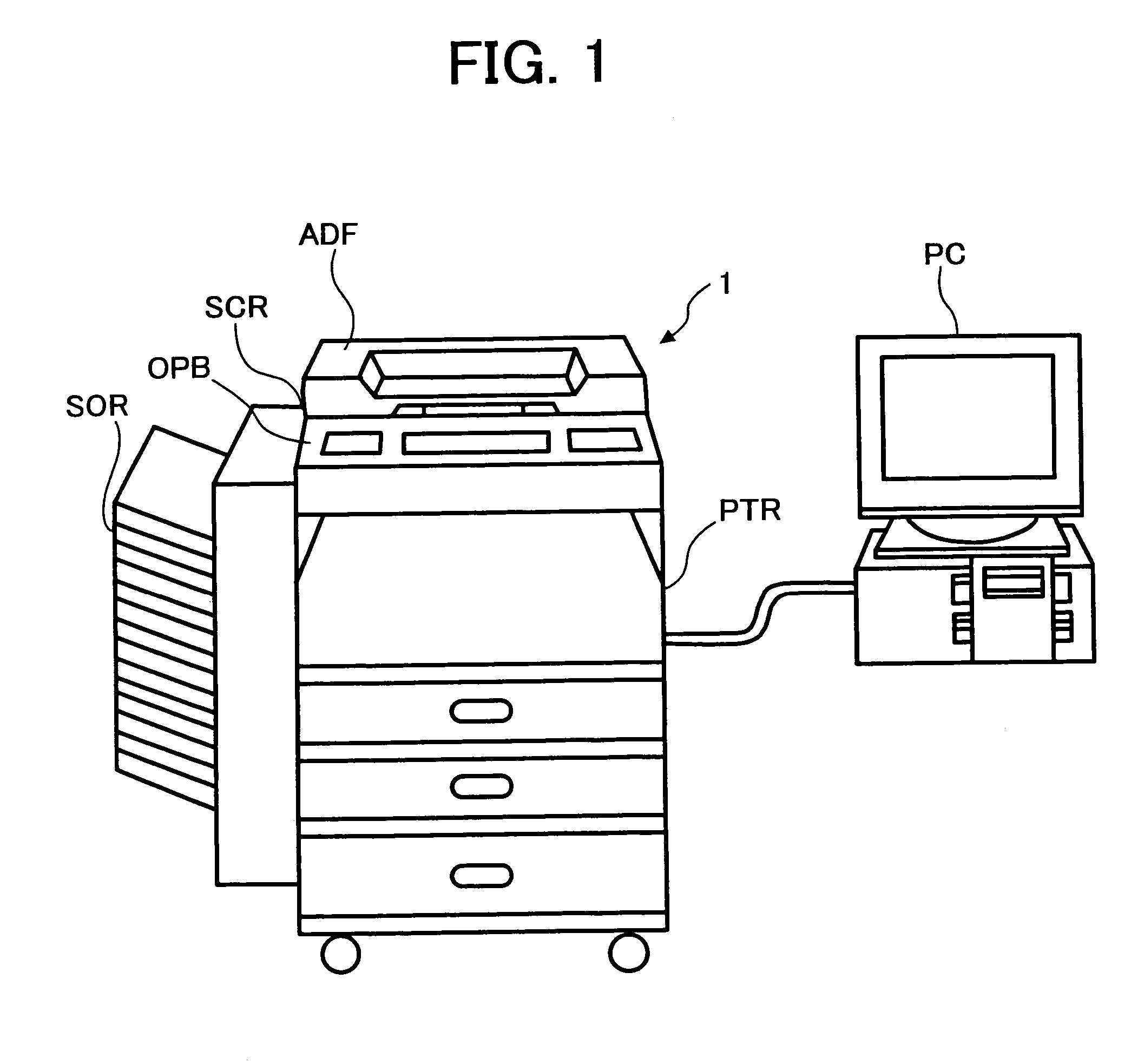
[0068]First, one example of the color image forming device in which the present invention is applied will be described. As is shown in FIG. 1, this color image forming device is a tandem drum type color image forming device, and is a digital color copier (1) which has a composite function, and in which a color printer PTR used as an image forming part, a scanner SCR used as an image reading device, an automatic original supply device ADF, a sorter SOR, an operating board OPB used as an operating part and the like are installed. This digital color copier (1) has a system construction which can itself produce copies of originals, or which can print out printing data constituting image information when such printing data is supplied from a host PC such as a personal computer or the like via a communications interface.

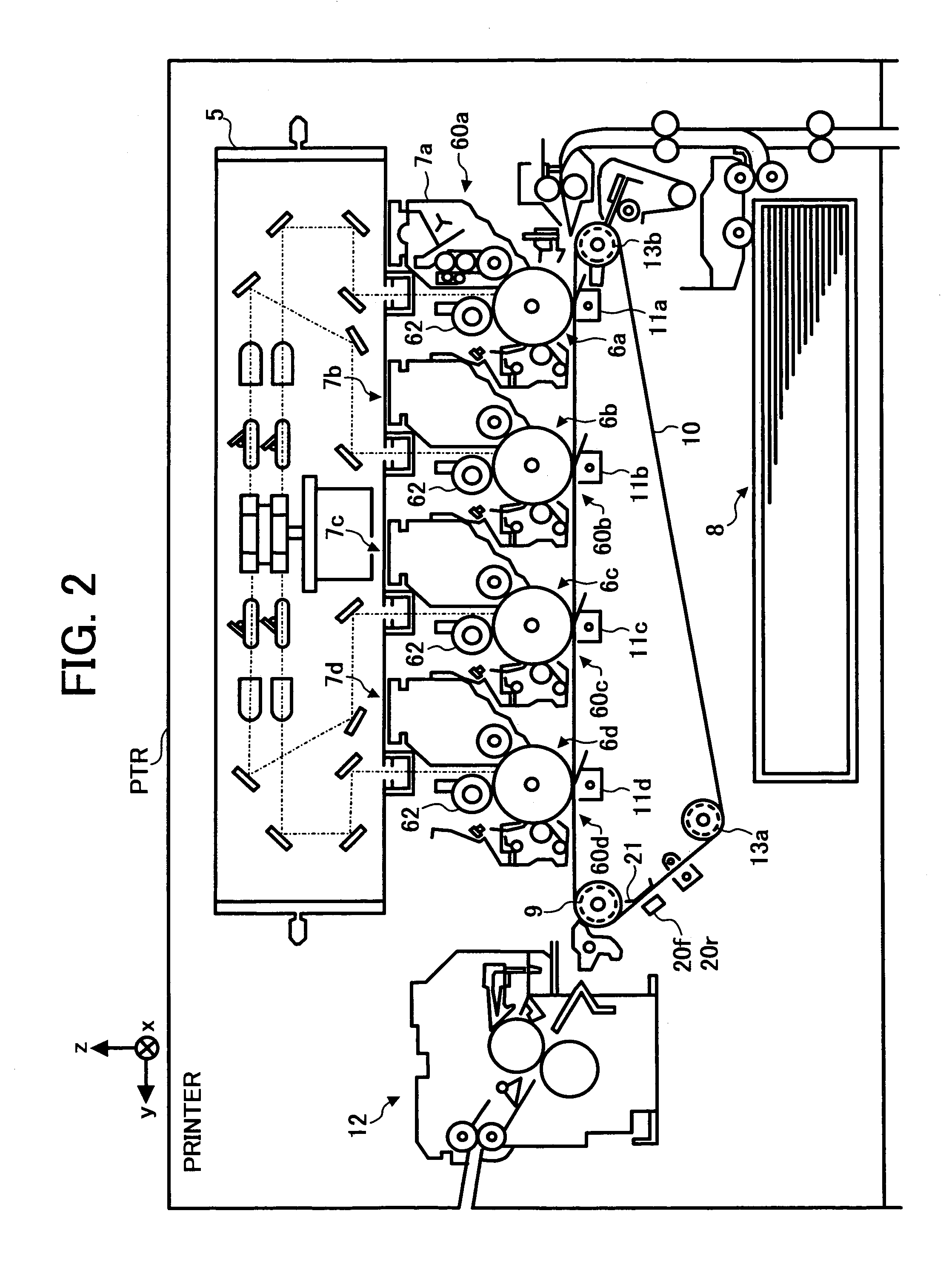
[0069]The construction of the abovementioned color printer PTR is shown in FIG. 2. After image data of respec...


PUM


Abstract

A color deviation detection device for a color image forming device which prevents the occurrence of color deviation that is attributable to the fact that the precision of color deviation detection is low, the replacement of photosensitive bodies or developing devices is itself a cause of fluctuation in the color deviation, and the precision of the part before and after replacement is slightly different. In the color deviation detection device, the spacing between marks of the reference color and other colors, the spacing between marks of the same color and the spacing between mark sets are set as the spacing between marks within the mark sets and the spacing between mark sets, so that when the amount of color deviation is calculated for a synthesized wave comprising two or more driving irregularity frequencies that are generated by the image carrying body driving system and the transfer driving system, the calculation error caused by this synthesized wave is within a range that allows correction of the deviation of the image of a plurality of colors.

Description

BACKGROUND OF THE INVENTION[0001]1. Field of the Invention[0002]The present invention relates to a color deviation detection method, a color deviation detection device, a color deviation detection and correction method, a color deviation detection and correction device, a color image forming device and a process cartridge which make it possible to increase the reliability of color deviation detection, greatly reduce the error caused by the arrangement of marks in test patterns, and increase the precision of color deviation correction.[0003]2. Description of the Related Art[0004]For example, color deviation detection methods for detecting the positional deviation of pixels of a plurality of colors in color image forming devices are disclosed in Japanese Patent No. 2,573,855, Japanese Patent Application Laid-Open No. 11-65208, Japanese Patent Application Laid-Open No. 11-102098, Japanese Patent Application Laid-Open No. 11-249380, Japanese Patent Application Laid-Open No. 2000-112205 ...

Claims


Application Information

Patent Timeline
Patent Type & Authority Patents(United States)
IPC IPC(8): G03G15/00G03G15/01B41J2/525G03G15/16
CPCG03G15/01G03G2215/0161
Inventor KOBAYASHI, KAZUHIKO
Owner RICOH KK
Why Eureka
Try Eureka