

Data transmit method and data transmit apparatus
a data transmission and data technology, applied in the field of data transmission methods and data transmission apparatuses, can solve the problems of deteriorating efficiency of use of data bus interfaces used by cpu, affecting the efficiency of data storage and audio data, so as to reduce the amount of data memory required and improve the efficiency of bus us
- Summary
- Abstract
- Description
- Claims
- Application Information
AI Technical Summary
Benefits of technology
Problems solved by technology
Method used
Image

Examples
embodiment 1
(Embodiment 1)
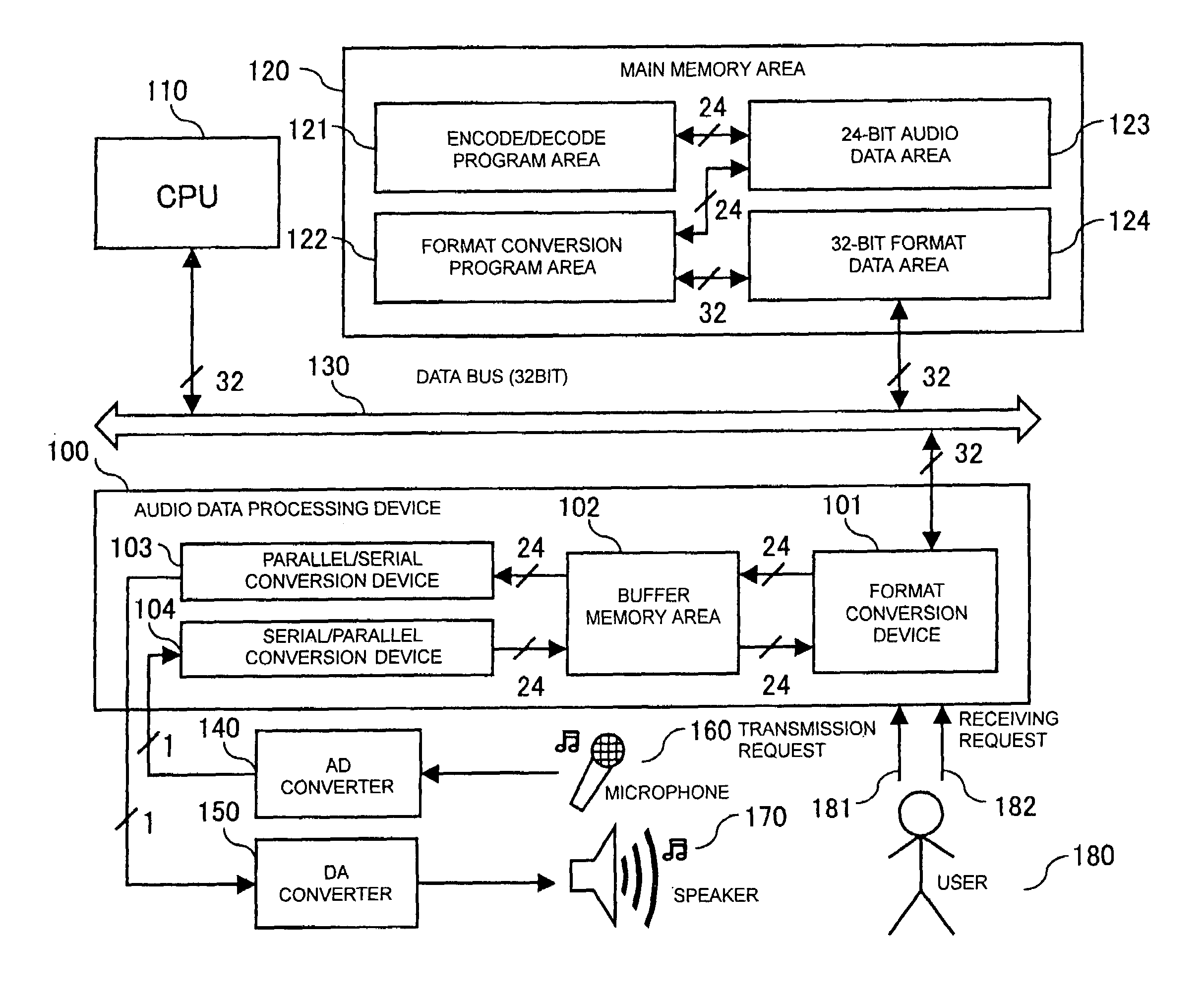
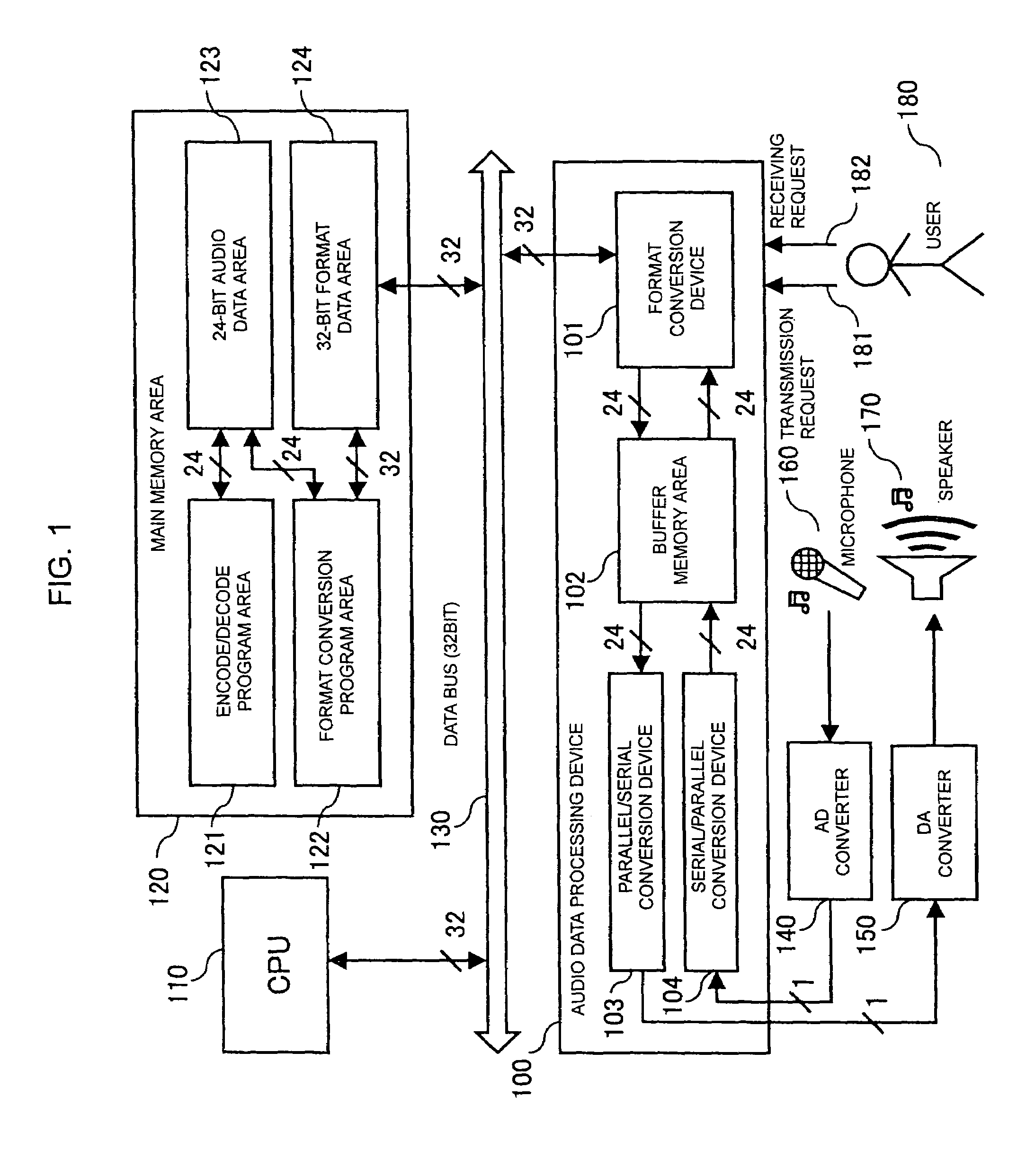
[0057]FIG. 1 is a block diagram that shows the entire structure of a data transmission apparatus in accordance with embodiment 1 of the present invention.
[0058]This data transmit apparatus is provided with an audio-data processing device 100, a CPU 110, a main memory area 120 and a data bus (32 bit) 130. The audio-data processing device 100 is constituted by a format conversion device 101, a buffer memory area 102, a parallel / serial conversion device 103 and a serial / parallel conversion device 104. The main memory area 120 is provided with an encode / decode program area 121, a format conversion program area 122, a 24-bit audio-data area 123 and a 32-bit format data area 124. Reference numeral 14 represents an AD converter, 150 represents a DA converter, 160 represents a microphone, 170 represents a speaker, 180 represents a user, 181 represents a transmission request and 182 represents a receiving request.
[0059]The audio-data processing device 100 is connected to the da...
embodiment 2
(Embodiment 2)
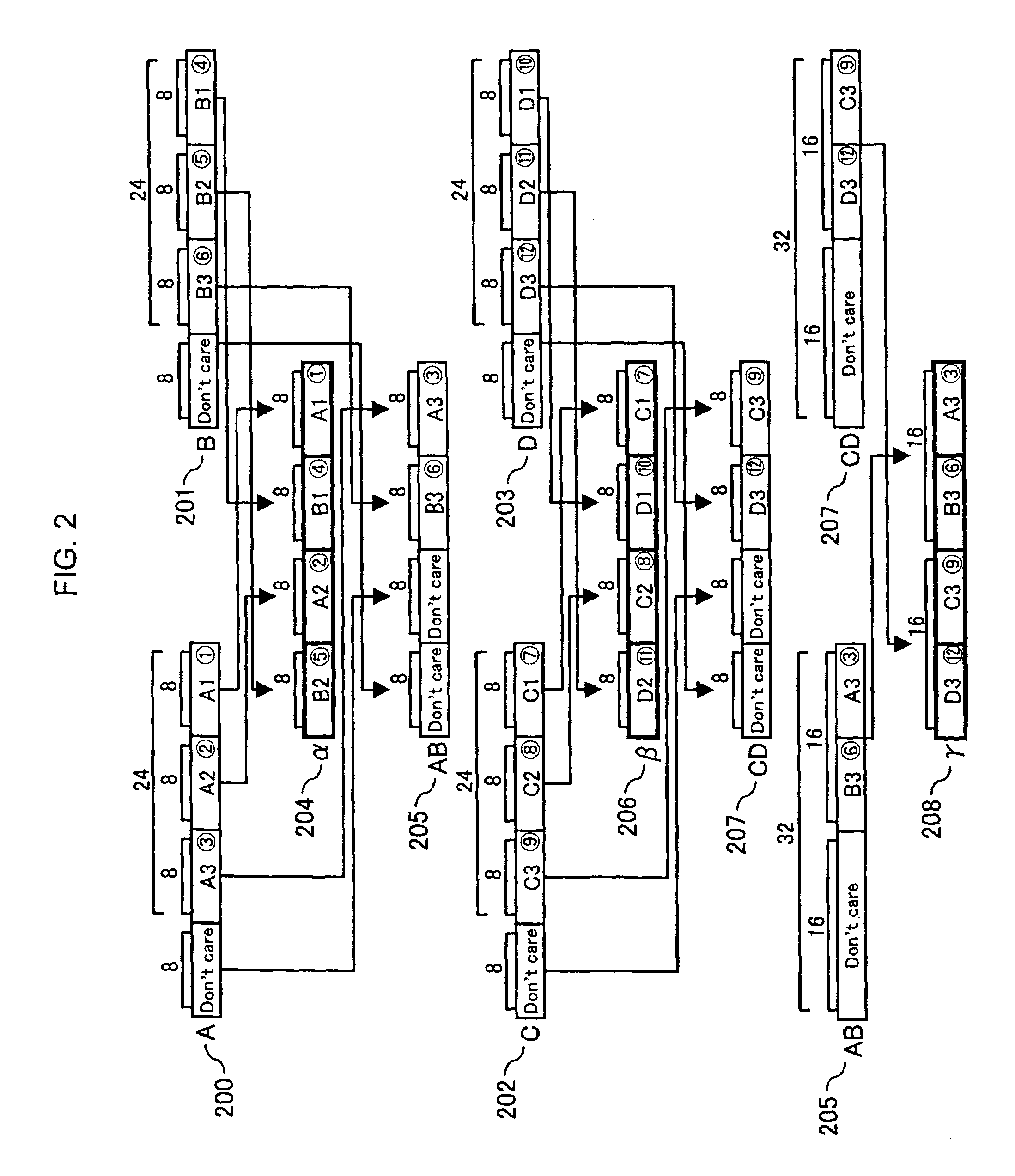
[0091]FIG. 2 is a conceptual drawing that shows operations of a transmitting conversion program in accordance with embodiment 2 of the present invention.
[0092]Data A 200 is 24-bit audio data constituted by packets of A1, A2 and A3, each having 8 bits. Data B 201 is 24-bit audio data constituted by packets of B1, B2 and B3, each having 8 bits. Data C 202 is 24-bit audio data constituted by packets of C1, C2 and C3, each having 8 bits. Data D 203 is 24-bit audio data constituted by packets of D1, D2 and D3, each having 8 bits. These data are inputted to a transmitting conversion program.
[0093]Data α204 is 32-bit format data constituted by packets of A1, B1, A2 and B2, each having 8 bits. This is outputted as the resulting data after operations using data A200 and data B201 as input data. Data AB 205 is constituted by packets of A3 and B3, each having 8 bits. This data is 32-bit format data with the higher-order 16 bits being defined as “Don't care”, and outputted after o...
embodiment 3
(Embodiment 3)
[0103]FIG. 3 is a conceptual drawing that shows operations of a receiving conversion program in accordance with embodiment 3 of the present invention.
[0104]Data α300 is 32-bit format data constituted by packets of A1, A3, B1 and B3, each having 8 bits. Data β301 is 32-bit format data constituted by packets of A2, C2, B2 and D2, each having 8 bits. Data γ302 is 32-bit format data constituted by packets of C1, C3, D1 and D3, each having 8 bits. These data are inputted to a receiving conversion program.
[0105]Data β′303 is constituted by packets of C2, B2 and D2, each having 8 bits. This data is 32-bit format data with the higher-order 8 bits being defined as “Don't care”, and outputted after operations carried out by using data β301 as input data. Data A304 is constituted by packets of A1, A2 and A3, each having 8 bits. This data is 32-bit format data with the higher-order 8 bits being defined as “Don't care”, and outputted after operations carried out by using data α300 ...
PUM
 Abstract
Description
Claims
Application Information