Workpiece-transfer device

a technology of transfer device and workpiece, which is applied in the direction of metal-working feeding device, stacking article, de-stacking article, etc., can solve the problems of increased cost, complicated configuration of the entire device, insufficient degree of simplification and cost reduction, etc., and achieves the effect of reducing costs and simplifying the configuration

Inactive Publication Date: 2006-11-07
MURATA MASCH LTD
View PDF33 Cites 20 Cited by
  • Summary
  • Abstract
  • Description
  • Claims
  • Application Information

AI Technical Summary

Benefits of technology

[0013]This configuration provides a square layout of the facility, including the workpiece-machining device, the workpiece-storage device, and the workpiece-transfer device. Such a square layout enables the floor area of the factory to be used more effectively.
[0014]According to the present invention, the workpiece-storage device has a product-housing section and a material-housing section, and the rectangular coordinate system movement means can move the traveling body to the product- and material-housing sections so that the traveling body can be moved into position and load a material workpiece gripped by the gripping means...

Problems solved by technology

The conventional loader and unloader execute loading and unloading exclusively, so both devices must be installed in order to perform both of these operations, resulting in the complicated configuration of the entire device and increased costs.
Due to the use of shared parts, the loader and unloader sharing the rails for the traveling body simplifies the configuration and reduces costs compared to exclusive devices that are independent of each other, but the degree of simplification and cost reduction are insufficient.
Consequently, in ...

Method used


Image

  • Workpiece-transfer device
  • Workpiece-transfer device
  • Workpiece-transfer device

Examples


Embodiment Construction

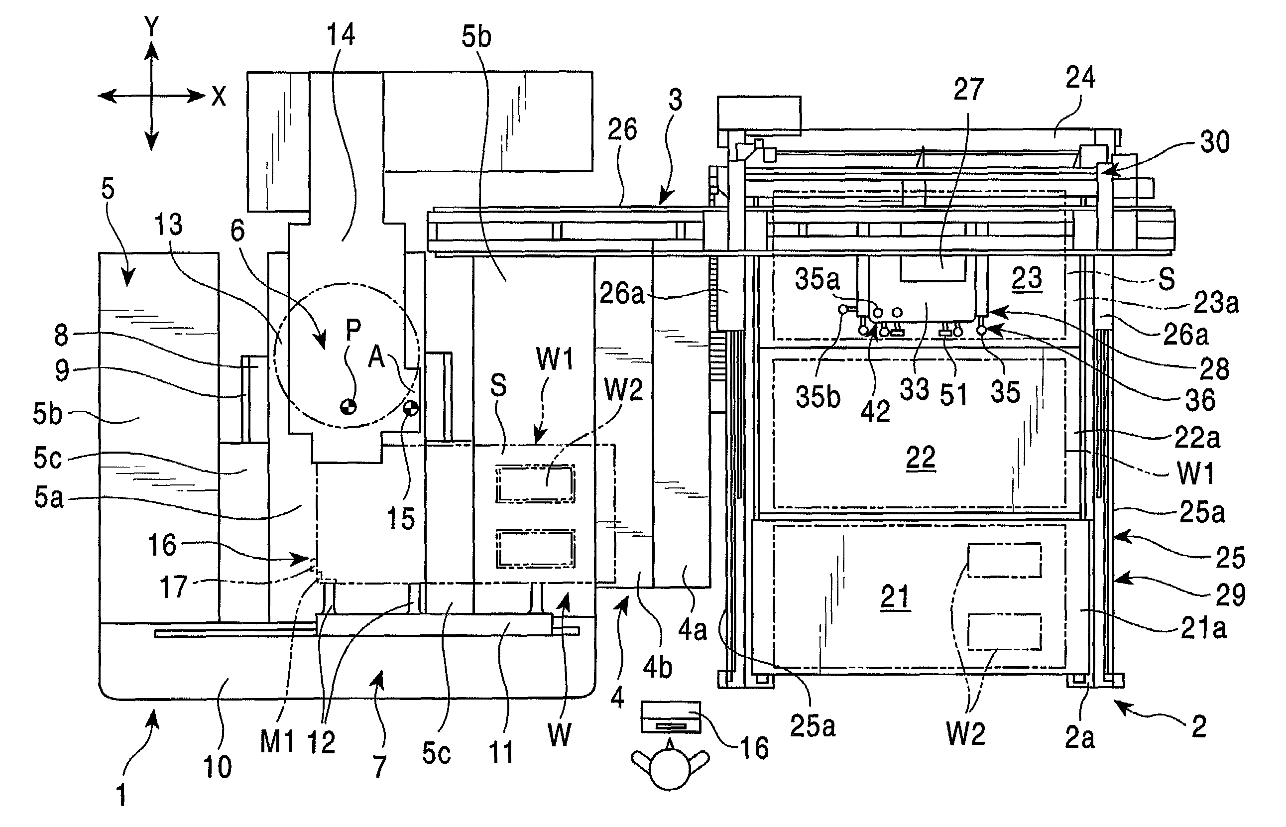
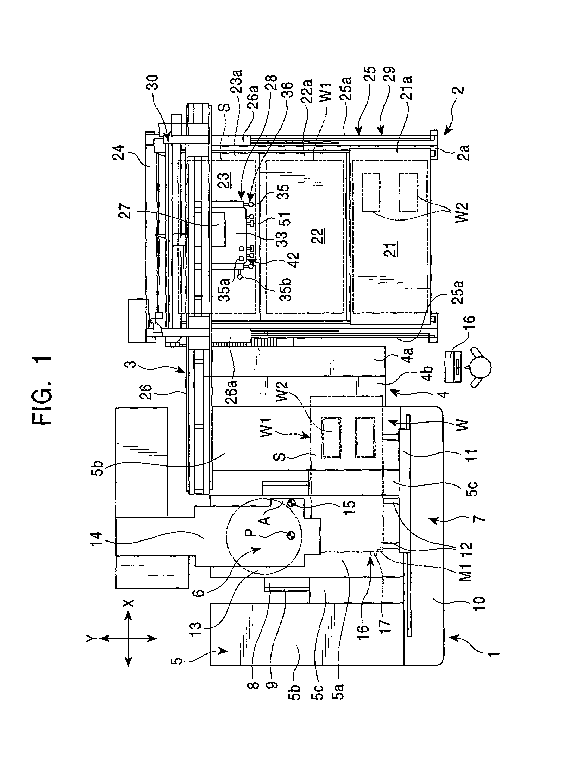
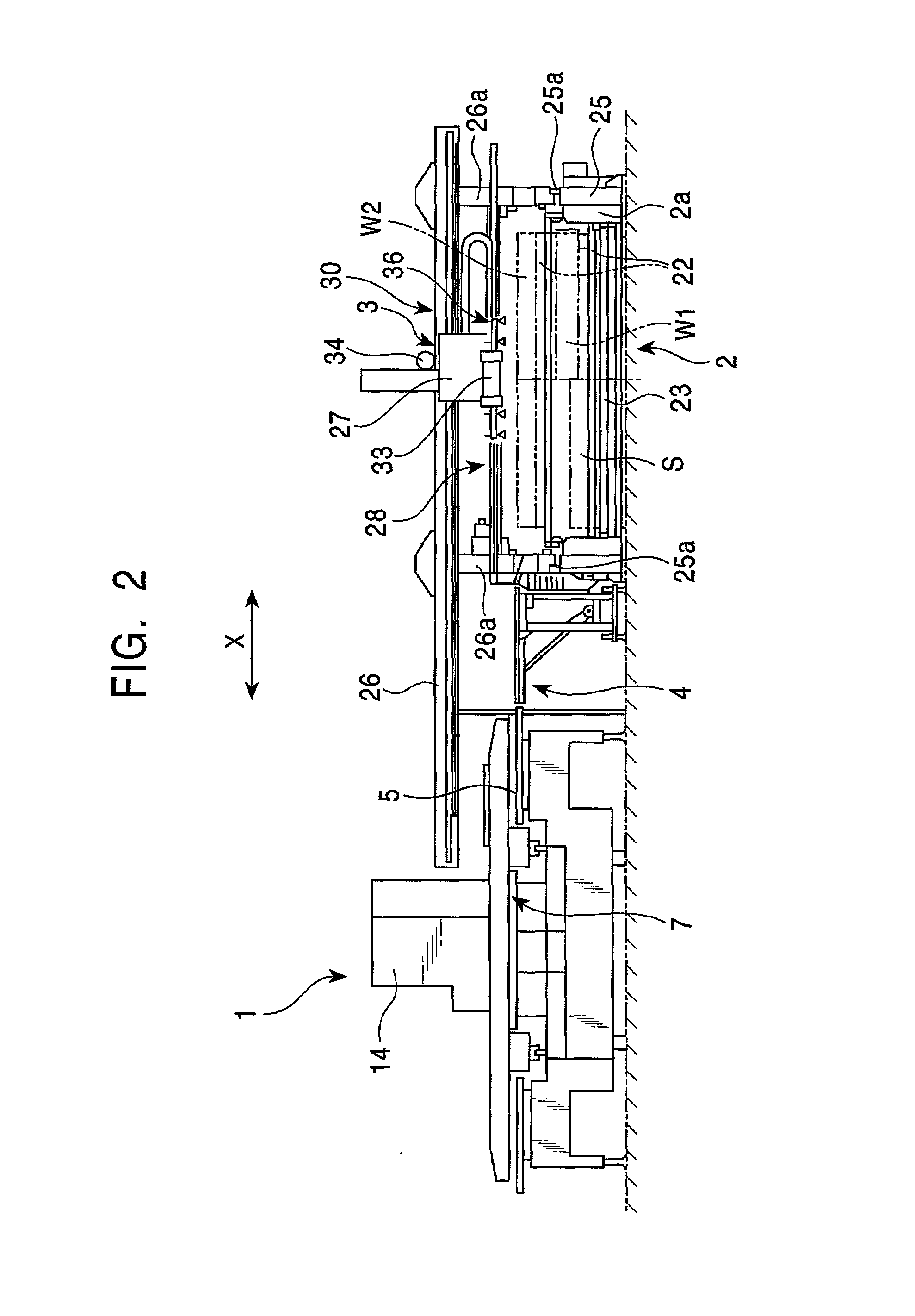
[0027]One embodiment of the present invention is described in conjunction with the FIGS. 1 to 11. As shown in the top view in FIG. 1, a workpiece-storage device 2 is installed at the side of a workpiece-machining device 1, and a workpiece-transfer device 3 for transferring a workpiece W (material workpiece W1 and a product workpiece W2) is installed between the workpiece-machining device 1 and the workpiece-storage device 2. The workpiece-machining device 1 and the workpiece-storage device 2 are placed at small intervals so that an auxiliary table 4 may be installed between these devices and so that a control panel 16 may be installed between them and in front of them.

[0028]The workpiece-machining device 1 comprises a table 5 on which the workpiece W is placed, a machining section 6 for machining the workpiece W on the table 5, and a workpiece-feeding device 7 for moving the workpiece W located on the table 5. In the workpiece-feeding device 7, a cross slide 11 capable of moving in ...


PUM

PropertyMeasurementUnit
Lengthaaaaaaaaaa

Abstract

The present invention provides a workpiece-transfer device that has functions for both loading and unloading workpieces, without requiring a workpiece-storage device to enable a function for replacing material and product workpieces with each other, and that requires only a simple configuration and low costs. A workpiece-transfer device loads a material workpiece W1 in a workpiece-machining device 1 and unloads a product workpiece W2 from the workpiece-machining device 1. A movement means with a rectangular coordinate system 30 is provided to move a traveling body 27 in a first direction along the direction in which the workpiece-machining device 1 and a workpiece-storage device 2 stand in a line (direction X) as well as in a second horizontal direction orthogonal to the first direction (direction Y). The traveling body 27 includes a gripping means 28 for gripping a material or product workpiece W1 and W2.

Description

FIELD OF THE INVENTION[0001]The present invention relates to a workpiece-transfer device for loading a material workpiece, such as a sheet, a sheetmetal, in a workpiece-machining device and unloading a product workpiece therefrom.BACKGROUND OF THE INVENTION[0002]A loader or an unloader annexed to a workpiece-machining device conventionally comprises a traveling body that travels in the direction in which a workpiece-machining device and a workpiece-storage device are separated from each other, the traveling body having suction pads to suck the top surface of a workpiece for transfer. Such a loader and an unloader are designed to be independent of each other or to share rails for the traveling body.[0003]The conventional loader and unloader execute loading and unloading exclusively, so both devices must be installed in order to perform both of these operations, resulting in the complicated configuration of the entire device and increased costs. Due to the use of shared parts, the loa...

Claims


Application Information

Patent Timeline
IPC IPC(8): B26D7/06B21D28/36B21D43/00B21D43/18B21D45/04B23Q7/04B23Q7/10B23Q7/14B25B11/00B65G47/91B65H3/08B65H29/24
CPCB23Q7/04B23Q7/10B25B11/005Y10T83/207Y10T83/2185Y10T83/4632Y10T83/4637Y10T83/464Y10T83/647Y10T83/2037
Inventor NAKAJIMA, AKIO
Owner MURATA MASCH LTD
Why Eureka
Try Eureka