Ejector pin and method

a technology of ejector pins and molds, applied in the field of ejector pins and methods for molds, can solve the problems of increasing mold down time, limiting the number of flow options available, and no provision is disclosed for removing the core pin, etc., and achieves the effects of convenient installation, quick and easy rotation, and easy removal

Inactive Publication Date: 2006-11-07
WIEDER KLAUS A
View PDF58 Cites 11 Cited by
  • Summary
  • Abstract
  • Description
  • Claims
  • Application Information

AI Technical Summary

Benefits of technology

[0026]Objects, features, and advantages of the present invention include a mold insert that is easy to install in a mold; is easily removed; is quick and easy to rotate; is quick and easy to change; minimizes mold downtime; can be installed on an ejector pin; and is an insert that is rugged, simple, flexible, reliable, and durable, and which is of economical manufacture and is easy to assemble, install, and use.
[0027]Objects, features, and advantages of the present invention include an ejector pin that is easy to install in a mold; maintains location of an insert mounted thereto; is efficient to manufacture because it is cut to length after initial manufacture; and is an ejector pin that is rugged, simple, flexible, reliable, and durable, and which is of economical manufacture and is easy to assemble, install, and use.

Problems solved by technology

However, not all of the cavities are needed at all times. Thus, a mechanism is needed which can selectively direct flow to one or more cavities or none of the cavities, if desired.
Unfortunately, no provision is disclosed for removing the core pin without knocking out the entire mechanism by inserting a pin or screwdriver through a bore in the backside of the mold against the retainer.
Such a process is time consuming which, in turn, increases mold down time, which is very costly.
Moreover, only four core pin positions are disclosed, limiting the number of flow options available.
To rotate the core pin to redirect flow, the pin must be pushed into the retainer which is time consuming and difficult.
Such an insert is also ill-suited for imprinting an indicia, such as the date, time and material type into the hardenable material.

Method used


Image

  • Ejector pin and method
  • Ejector pin and method
  • Ejector pin and method

Examples


Embodiment Construction

I. Introduction

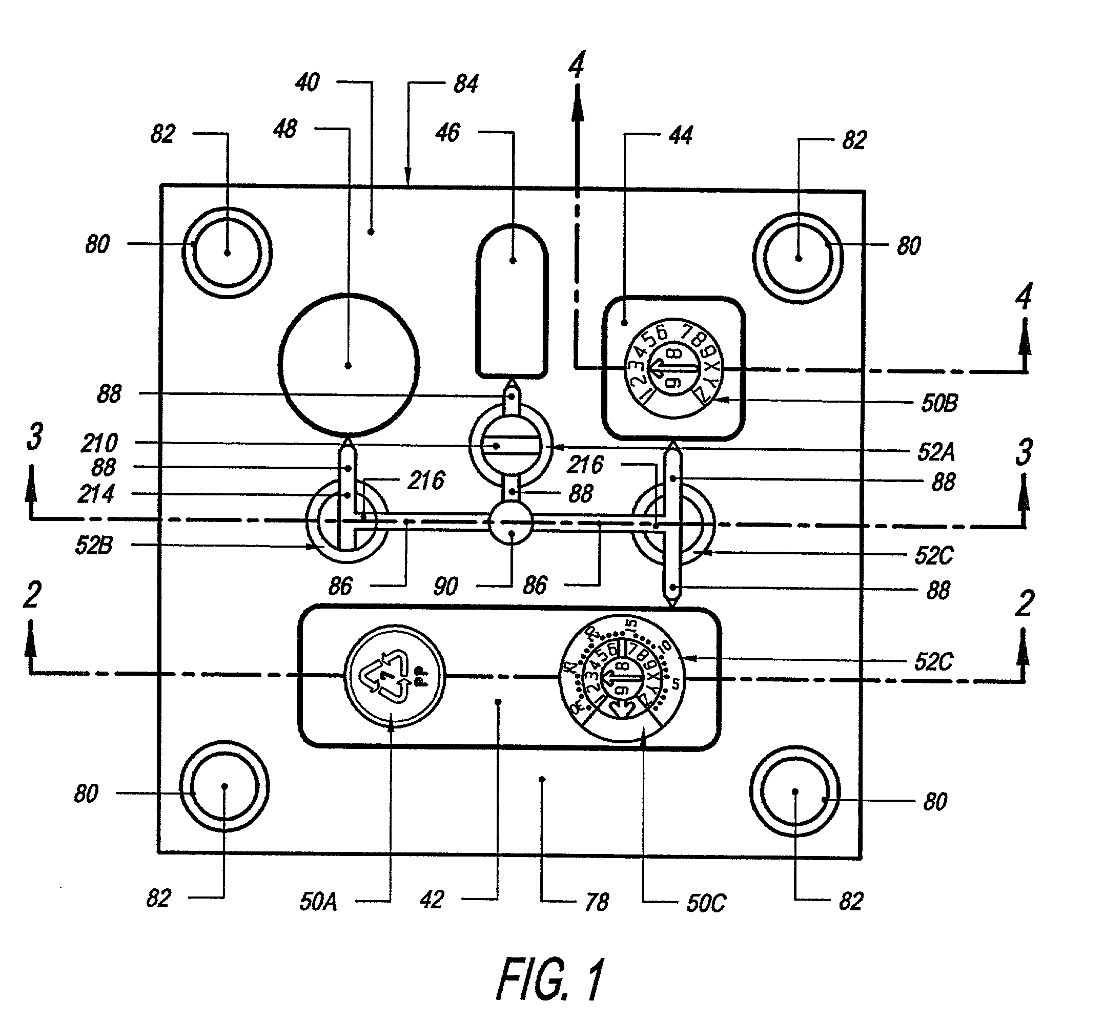
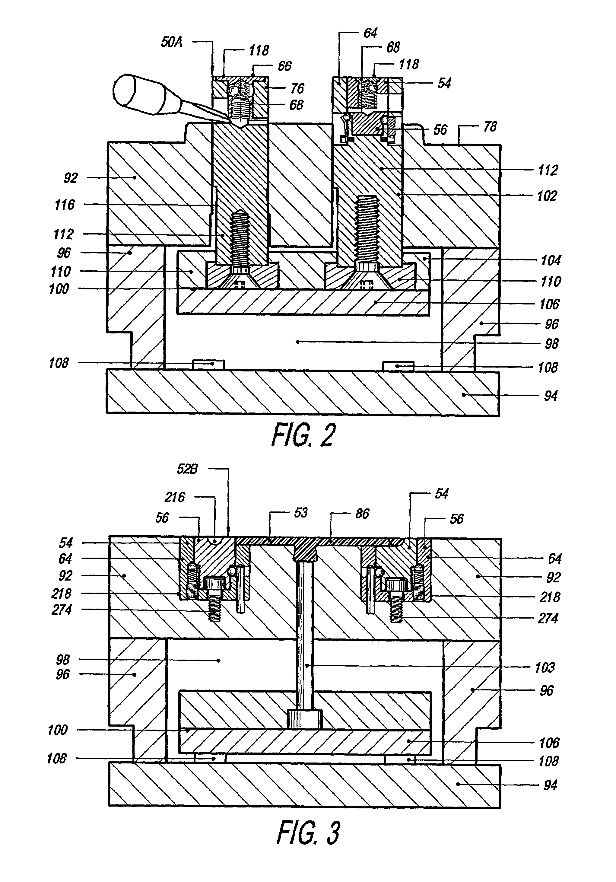
[0054]FIGS. 1–4 depict a mold 40 having a plurality of cavities 42, 44, 46, and 48, and a plurality of inserts 50a–50c and 52a–52c of this invention for controlling the flow of material 53 (FIG. 3) being communicated to one or more of the cavities 42, 44, 46 and 48 and for imparting an indicia to material 53 in one or more of the cavities 42 and 44 as the material 53 in the cavities 42 and 44 hardens. Each insert 50 and 52 includes a rotating mechanism to enable it to rotate relative to the mold 40. Each insert 50 and 52 preferably is indexable to certain positions to control or divert flow or to select a particular indicia to imprint into the hardenable material 53 in the mold cavity.

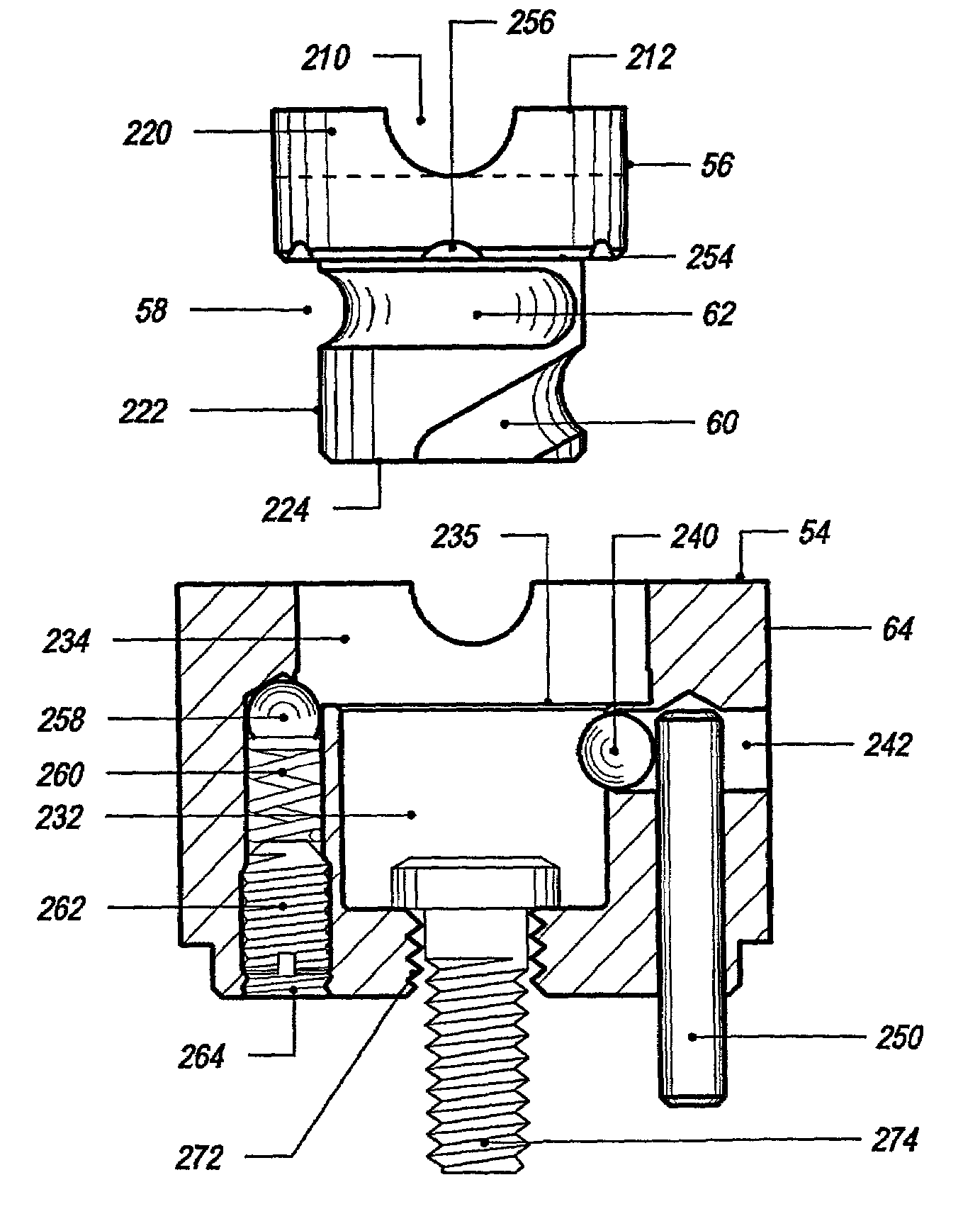
[0055]Referring to FIG. 5, one preferred rotating mechanism 54 has a plug 56 with a circular groove 58 that is received in a receiver that, in this instance, comprises a cup 64. The groove 58 has a helical portion 60 that enables the insert to be easily removed when rotated beyond a cert...


PUM

PropertyMeasurementUnit
sizesaaaaaaaaaa
diameteraaaaaaaaaa
depthaaaaaaaaaa

Abstract

An insert for a mold comprising a plug, having an insert face, and a receiver defined by a sidewall with one of the plug and the receiver having a groove that receives a guide that extends from the other of the plug and the receiver so as to facilitate rotation of the plug while opposing withdrawal of the plug. In one preferred embodiment, the groove has an inclined entranceway, that facilitates plug insertion and removal, and a transverse portion and extends circumferentially no more than about one and one-quarter rotation about the plug. In another embodiment, the guide is resiliently urged outwardly from the plug to ride in a groove in the sidewall and the sidewall has an access port for prying free the plug from the receiver. A detent assembly comprised of notches on the plug and a detent carried by the receiver permit the plug to be selectively indexed. The insert can be mounted to or carried by an ejector pin having a head constructed and arranged to prevent rotation of the pin during mold operation. In one preferred pin, a portion of the barrel is machined and hardened before shipment to another location, typically to an end user, where the unmachined portion is cut to length before machining the head and remainder of the barrel.

Description

CROSS-REFERENCE TO RELATED APPLICATION[0001]This application is a continuation of U.S. application Ser. No. 09 / 177,267 filed Oct. 22, 1998, now U.S. Pat. No. 6,308,929 on Oct. 30, 2001.FIELD OF THE INVENTION[0002]The present invention relates to an ejector pin and method for a mold and more particularly to an ejector pin blank, ejector pin, and method for making an ejector pin.BACKGROUND OF THE INVENTION[0003]It is common for molds of all kinds to be equipped with multiple mold cavities to increase production. However, not all of the cavities are needed at all times. Thus, a mechanism is needed which can selectively direct flow to one or more cavities or none of the cavities, if desired.[0004]One such mechanism is disclosed in U.S. Pat. No. 5,208,053 and consists of three pieces, a retainer, a core pin and an outer casing. Unfortunately, no provision is disclosed for removing the core pin without knocking out the entire mechanism by inserting a pin or screwdriver through a bore in t...

Claims


Application Information

Patent Timeline
Patent Type & Authority Patents(United States)
IPC IPC(8): B41B11/62B29C45/27B29C45/37
CPCB29C45/2703B29C45/374B22C23/00
Inventor WIEDER, KLAUS A.
Owner WIEDER KLAUS A
Why Eureka
Try Eureka