

Rod-shaped inserts in reactor tubes
a reactor tube and insert technology, applied in the direction of organic chemistry, lighting and heating apparatus, physical/chemical process catalysts, etc., can solve the problems of high exothermic reaction, inability to achieve significant improvement of heat transfer when applying (stainless steel), and expensive catalysts being used as inerts. , to achieve the effect of shortening the heating and/or cooling zone, reducing the cost of inserting and removing, and increasing the heating efficiency
- Summary
- Abstract
- Description
- Claims
- Application Information
AI Technical Summary
Benefits of technology
Problems solved by technology
Method used
Image

Examples
example 1
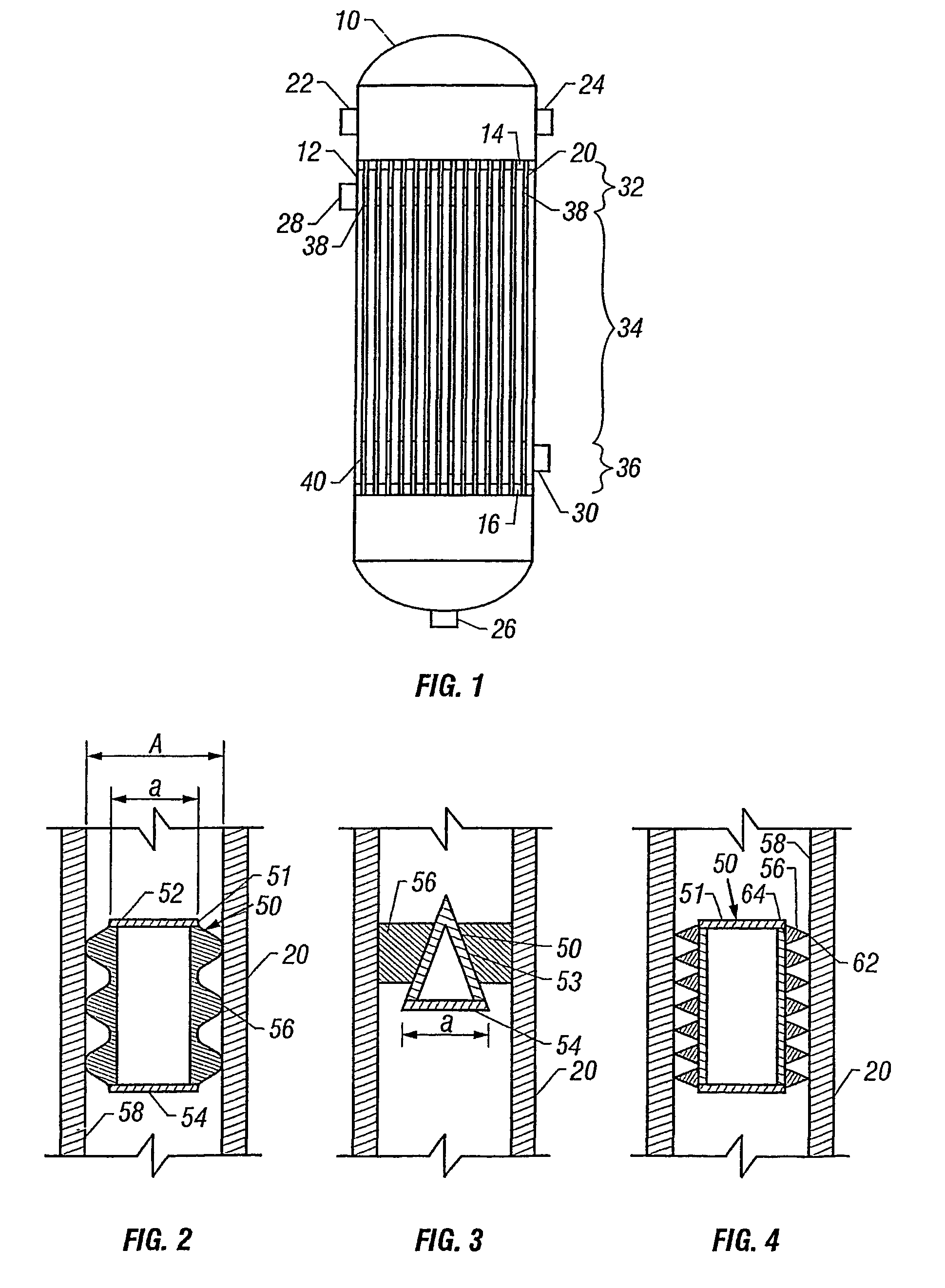
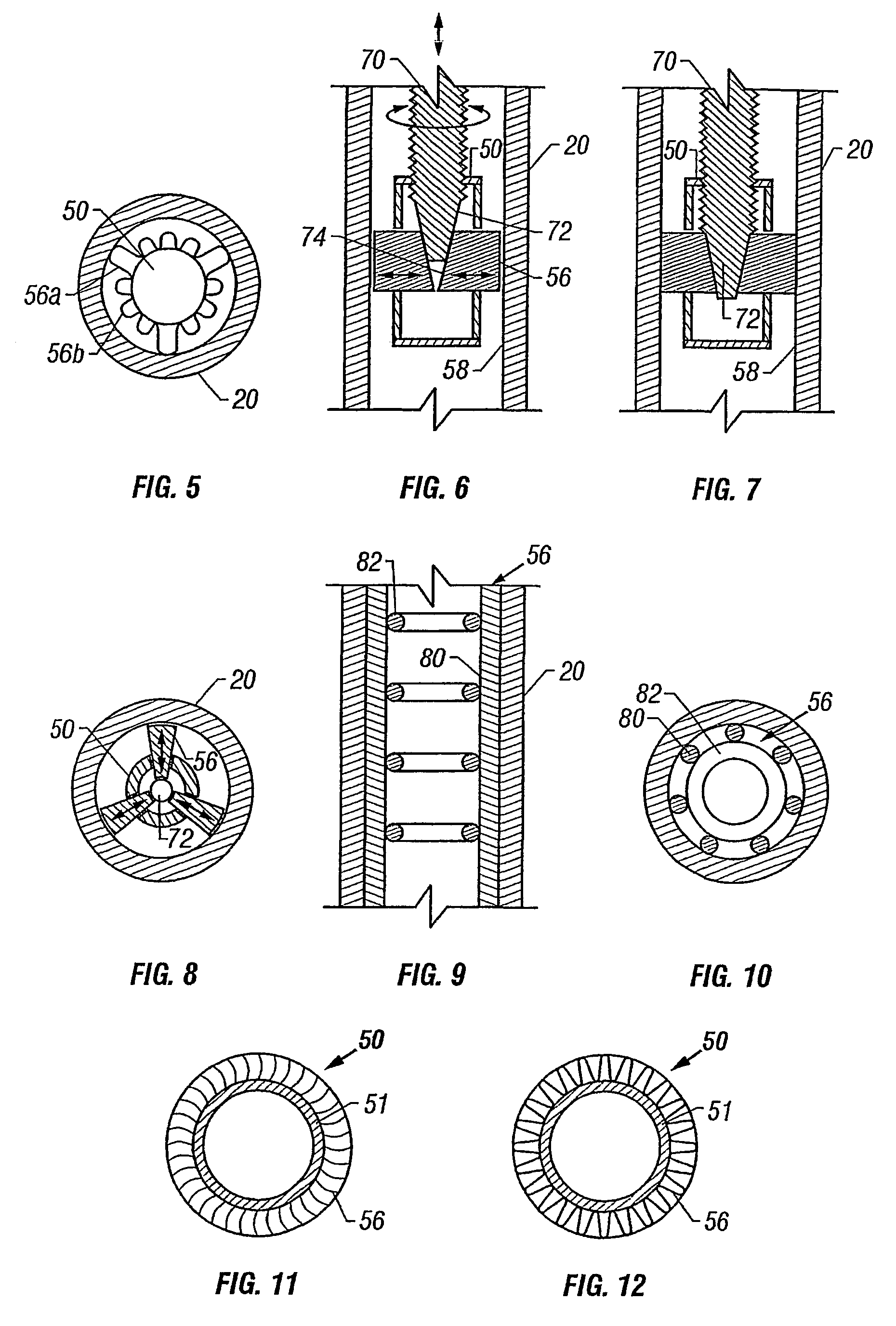
Insert
[0063]FIG. 11 is a schematic cross sectional end view of an insert. The insert 50 included a construction of 32 bent fins as protrusions 56, welded individually around a central core 51 or annulus, which is a hollow cylinder, closed at one end or both ends and having an outside diameter of 25 mm. The thickness of the fin material is 1 mm and the total height of each bent fin is 8.1 mm. The outer diameter of the construction is 38.5 mm and its length 35 cm.
example 2
Insert
[0064]FIG. 12 is a schematic cross sectional end view of an insert. The insert 50 included a construction of a 1 mm stainless steel plate formed into protrusions 56, that is, the plate was corrugated with corrugation length of 5 mm and a corrugation height of 6.75 mm, bent around the core 51, similar to such in Example 1. The outer diameter of the construction is 38.5 mm and its length 35 cm.
example 3
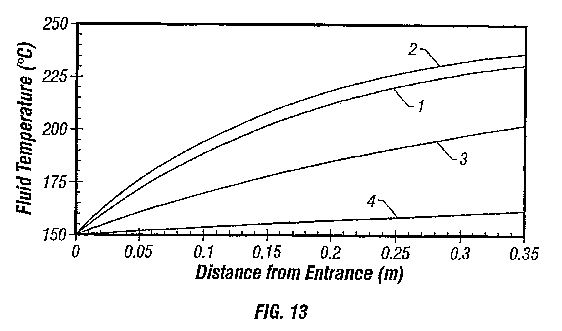
[0065]A reactor tube is used, having an internal diameter of 38.5 mm and a length of about 35 cm, that being about 3% of the total length of a typical commercial reactor tube. The reactor tube is charged with the inserts of Examples 1 and 2 (each also having a length of 3% of the total length of a typical commercial reactor tube), with the ring-formed particles, or left void, and is heated to 250° C. A gaseous mixture of methane (50%), ethylene (40%) and oxygen (10%) enters the reactor tube at a superficial velocity of 1 ms−1, 2000 kPa and 150° C.
[0066]The heat transfer inside the tube charged with the inserts of Examples 1 and 2 and the heat transfer inside the void tube is determined according to the heat transfer relations of V. Gnielinski, “Chem.-I.-Techn.”, 61, (1989), 160 / 61, assuming a state steady heat transfer, a constant heat transfer coefficient at the surface of the insert, a homogeneous material of the insert, no heat production, no resistance in heat condu...
PUM
| Property | Measurement | Unit |
|---|---|---|
| diameter | aaaaa | aaaaa |
| diameter | aaaaa | aaaaa |
| temperature | aaaaa | aaaaa |
Abstract
Description
Claims
Application Information