Scale pan mount for single-point or multi-point mounted scale pan

a technology of scale pan and scale pan, which is applied in the field of weighing cell, can solve the problems of high production and inventory costs, large diversity in the overall number, and different measurement resolutions of different weighing cells, and achieves the effect of keeping the number of sub-assemblies or assembly modules low and high flexibility

Active Publication Date: 2006-11-07
METTLER TOLEDO GMBH
View PDF6 Cites 0 Cited by
  • Summary
  • Abstract
  • Description
  • Claims
  • Application Information

AI Technical Summary

Benefits of technology

[0013]In a family of balance models in which the different types are often distinguished from each other by the size of the weighing pan and by the way in which the weighing pan is coupled to the weighing cell, in particular whether the weighing pan is coupled to the vertically movable parallelogram leg of the force-transfer mechanism at several (in most cases four) points or at a single point, e.g., through a conical support post, the weighing cell module according to the invention makes it possible to connect either type of weighing pan and thus offers a high degree of flexibility. Consequently, a large diversity of different models can be produced within a single design family of balances, while at the same time the number of subassemblies or assembly modules is kept low.
[0022]If even larger weighing pans are used with an arrangement of multiple support points, the two support beams can be joined by transverse connectors to form a frame on which the support points for the weighing pan are located. It should be mentioned at this point that the points of attachment of a weighing pan to a balance should be paced as close as possible to the border of the weighing pan in order to minimize the harmful effects of eccentrically positioned loads.
[0024]The weighing cell module according to the invention not only minimizes the number of different subassemblies for the connection of the weighing pan and for the overload protection device but is also designed with the aim of reducing further components of the balance, for example the calibration system, to a small number of variable elements in each subassembly.

Problems solved by technology

Balances of the existing state of the art have the problem that within a model family, the respective weighing cells for different maximum loads and different measurement resolutions can differ strongly from each other in regard to their overall design and their subassemblies.
Thus, a large number of variations exists among the subassemblies, which leads to high production and inventory costs.
However, although the devices disclosed in the prior art are designed to use some of the same individual components in more than one balance model, there is still a relatively large diversity in respect to the overall number of subassemblies.
Thus, weighing pans exceeding a certain size can no longer be held by means of a cone with a single-point connection to the weighing pan, because the effects of an eccentric position of the weighing load could have too large an influence on the weighing result.
The influence of laterally directed torques which can have an effect on the force-transfer mechanism and can ultimately cause its destruction increases with larger sizes of weighing pans.

Method used


Image

  • Scale pan mount for single-point or multi-point mounted scale pan
  • Scale pan mount for single-point or multi-point mounted scale pan
  • Scale pan mount for single-point or multi-point mounted scale pan

Examples


Embodiment Construction

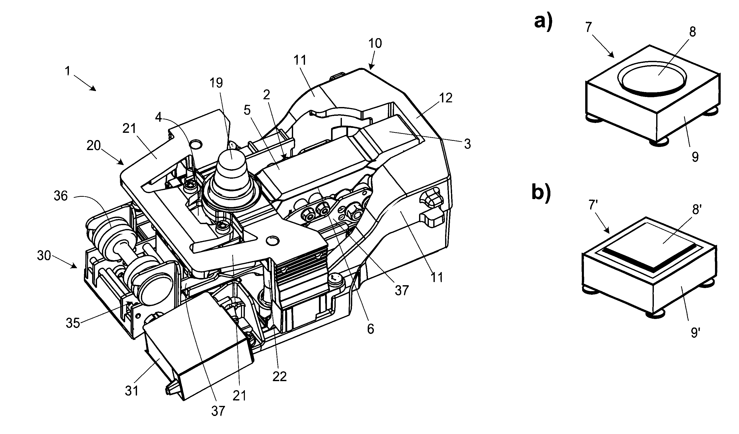
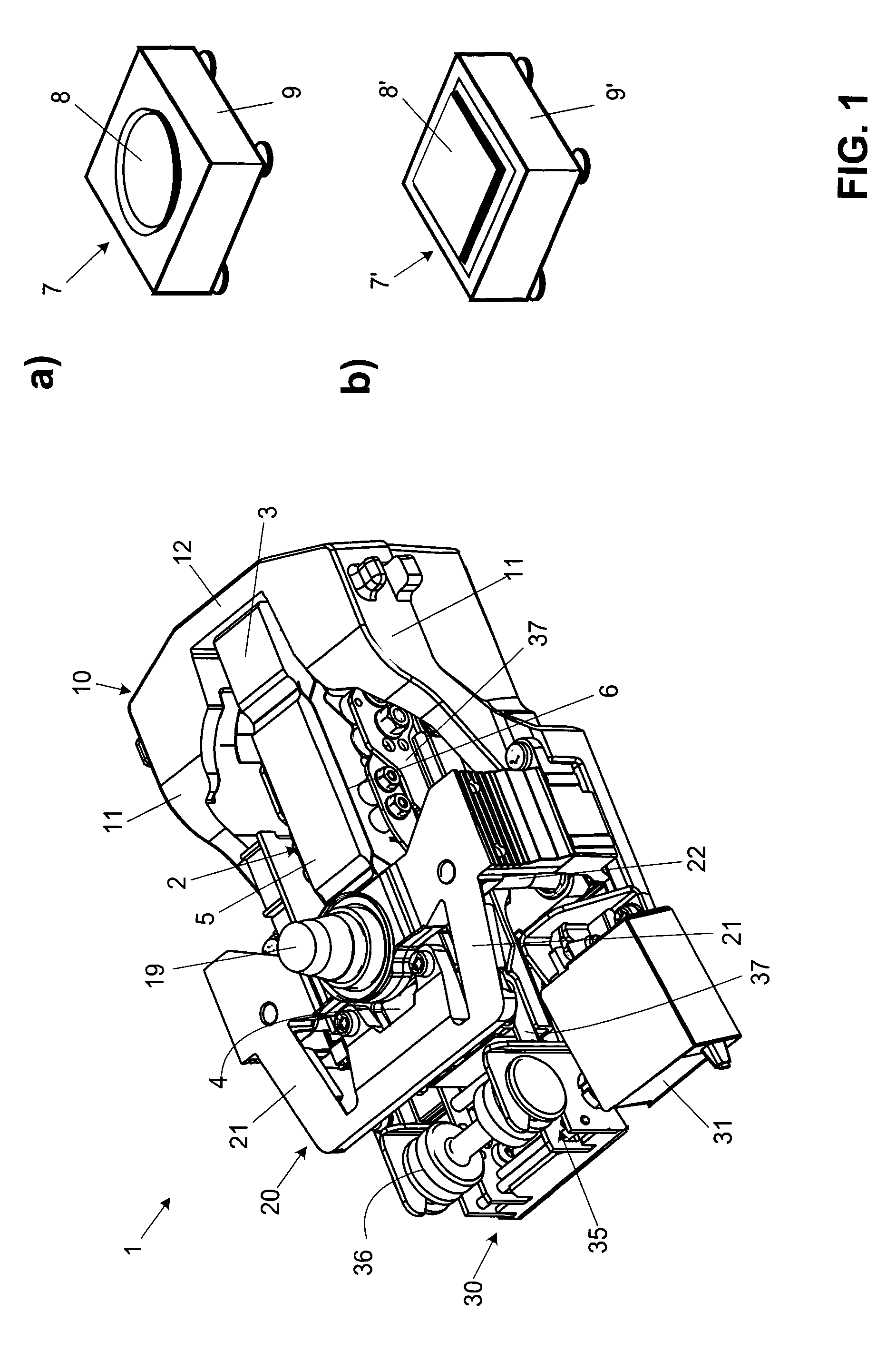
[0038]FIG. 1 gives a perspective view of parts of a weighing cell that are assembled to form a module which in the following will be referred to as weighing cell module and identified by the reference symbol 1. The preferred working principle for the weighing cell module 1 is electromagnetic force compensation. In addition to electrical and electronic components, the weighing cell module 1 includes a force-transfer mechanism 2 with a parallel-guiding linkage in which a stationary parallelogram leg 3 and a movable parallelogram leg 4 are connected by a pair of guide arms 5 (with only one guide arm 5 being visible in the drawing). The force-transfer mechanism is an integral part of a monolithic material block wherein the essential parts, i.e., the parallelogram, the lever arrangement, the coupling elements and the fulcrum supports (not visible in drawing), are separated from each other by material-free areas in the form of thin linear cuts 6 that traverse the material block in the dir...


PUM


Abstract

A weighing cell module with a force-transfer mechanism that includes a parallel-guiding linkage with a vertically movable parallelogram leg and a spatially fixed parallelogram leg, is equipped with a mounting area for a first weighing-pan support device with a single-point connection of a weighing pan, as well as with a mounting area for a second weighing-pan support device with a multiple-point connection, particularly a four-point connection, of a weighing pan, wherein the first and the second mounting area are each connected to the force-transfer mechanism. As a result, the weighing cell module can be used to manufacture different types of balances in a design family of balances, where each different type within the family is designed for a different maximum load.

Description

BACKGROUND OF THE INVENTION[0001]The invention relates to a weighing cell, more specifically a weighing cell module with a force-transfer mechanism that includes a parallel-guiding linkage with a vertically movable parallelogram leg and a spatially fixed parallelogram leg.[0002]In a weighing cell as the core element of a balance, the force-transfer mechanism—based on its design for a given maximum load and based on the accuracy that it is capable of achieving—essentially determines the range of applications that a balance can be used for.[0003]Commercially available balances are often structured in so-called families or series of balance models, where the balances within a model family have a similar appearance and are identified by similar model designations. A family of balances is often the result of either a single development project or of a group of mutually connected projects.[0004]Balances of the existing state of the art have the problem that within a model family, the resp...

Claims


Application Information

Patent Timeline
Patent Type & Authority Patents(United States)
IPC IPC(8): G01G21/18G01G21/00G01G21/23G01G21/24G01G23/01G01G23/02
CPCG01G21/244
Inventor KOPPEL, THOMASSCHILLING, PETERSCHNEIDER, FERDINANDBURKHARD, HANS-RUDOLPH
Owner METTLER TOLEDO GMBH
Why Eureka
Try Eureka