Brushless direct current motor

a direct current motor and brushless technology, applied in the direction of rotating magnets, synchronous machines with stationary armatures, windings, etc., can solve the problems of low efficiency, ineffective utilization of winding space in these kinds of motors, and motors that need to have a comparatively large volume, so as to maximize the number of cogging cycles and achieve the same operating performance , the effect of low cogging torqu

Inactive Publication Date: 2006-11-07
MINEBEA CO LTD
View PDF4 Cites 5 Cited by
  • Summary
  • Abstract
  • Description
  • Claims
  • Application Information

AI Technical Summary

Benefits of technology

[0007]The invention is based on the realization that the winding spaces, which in known motors contain opposed windings of the same phase and thus do not contribute to the build up of torque, can be reduced in order to create space for windings which make a contribution to the build up of torque. To this effect, the pole bridges for each stator pole group are moved closer together, whereby the minimum spacing of these pole bridges should correspond approximately to the width of the associated pole gaps. The small winding space thus formed may remain empty while the adjoining stator pole slots are enlarged and can accordingly accommodate more winding wire. Irrespective of the combination of the number of rotor poles and the number of stator slots, the motor according to the invention thus does not have any adjoining opposed windings of the same phase that do not contribute to the build up of torque. In fact, these winding sections are eliminated and the stator slot provided between the two stator poles of a stator pole group for this purpose in the prior art is reduced as far as possible, i.e. the pole bridges of the stator poles concerned are preferably moved closer together to the width of a stator pole gap, making considerably more winding space available for the other windings. Thus for the same combinations of the number of rotor poles and the number of stator slots, a significant improvement in the efficiency of the motor can be achieved.
[0008]In one embodiment, one or two stator pole groups are provided for each phase, each stator pole group being formed from two stator poles. In this way the stator pole groups, in whose intervening spaces no winding sections are provided, are distributed evenly over the stator, enabling a symmetric construction to be achieved and consequently a simple and low-cost manufacturing process to be realized.
[0010]The spacing between two pole bridges of a stator pole group, in whose intervening space no winding sections have been provided, preferably corresponds to the width of the stator pole gap between two adjoining pole heads. On the one hand, this arrangement allows unused winding space to be reduce to a minimum and, on the other hand, provides a DC motor in which the numbers of rotor poles and stator slots as well as the relative position of the rotor poles to the stator pole heads remain unchanged compared to motors of the prior art. At a higher output, this kind of motor can achieve the same operating performance in terms of torque ripple and cogging torque as a known motor having a corresponding combination of pole / slot numbers.
[0011]In an embodiment, the product of the number of stator poles and the number of rotor poles is the smallest number which can be divided in whole numbers by both the number of stator poles as well as by the number of rotor poles. In this embodiment, the respective angular offsets of each rotor pole differ from each other with respect to the corresponding opposing pole heads. As a result, the number of cogging cycles is maximized. An even distribution of cogging torque and thus a minimization of cogging torque is achieved. For example, in the case of a motor having nine slots and 16 poles, there is very low cogging torque at 144 cogging torque cycles per rotation. (144 is the smallest number that can be divided by both 9 and 16.) The higher the number of cycles, the lower is the cogging torque. This then goes to produce a very smooth running performance with low cogging torque and low torque ripple or fluctuations in the driving torque.
[0012]In another embodiment, at least one stator pole is disposed between two adjoining stator pole groups, the phase of the stator pole differing from the phases of the adjoining stator poles. This goes to ensure that stator pole groups whose pole bridges are disposed with only a small spacing between them are separated by an “unchanged” stator pole, thus simplifying the construction.
[0013]The motor preferably has nine stator slots and two rotor poles, nine slots and 16 rotor poles, 15 slots and four rotor poles or 18 slots and four rotor poles. DC motors having these combinations of the number of poles and the number of slots produce winding patterns in which two opposed windings of the same phase are located side by side in a stator slot, so that the winding sections in this stator slot do not contribute to the build up of torque. The respective winding sections can thus be eliminated and, according to the invention, the corresponding winding spaces can be reduced to the width of a stator pole gap, allowing the remaining stator pole slots to be increased as winding spaces.

Problems solved by technology

The winding space in these kinds of motors is consequently not utilized effectively, which means that the motors need to have a comparatively large volume should a certain motor output be required.
This results in low efficiency and relatively high costs in the manufacture of such a motor.

Method used


Image

  • Brushless direct current motor
  • Brushless direct current motor
  • Brushless direct current motor

Examples


Embodiment Construction

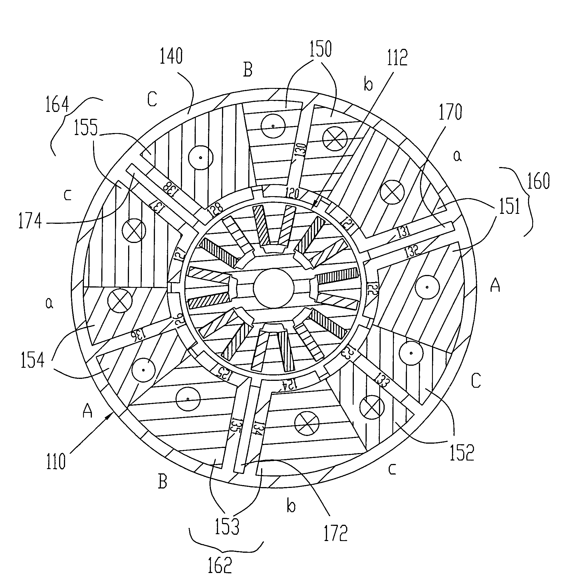
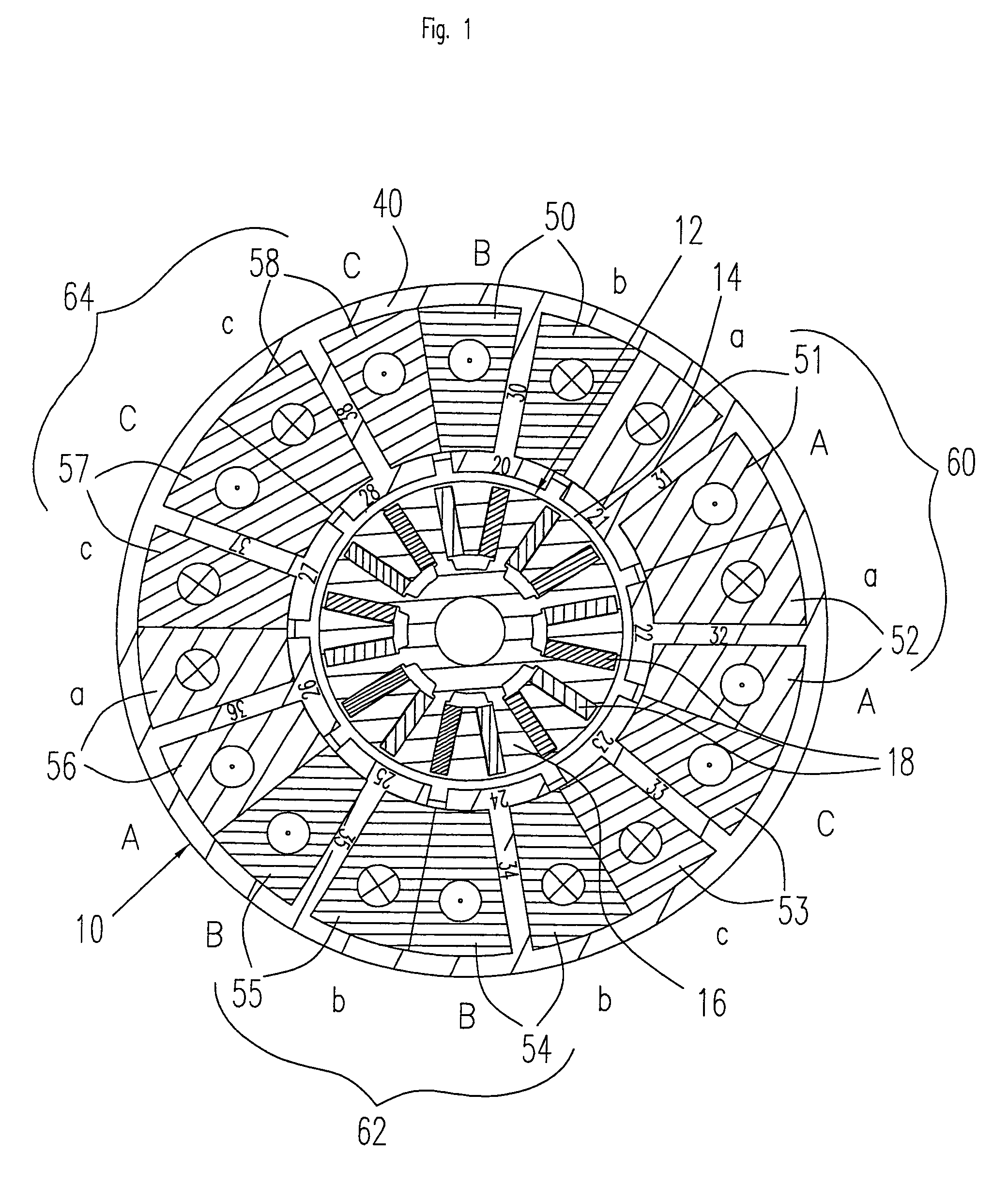
[0018]FIG. 1 shows a motor according to the prior art having nine slots and 16 rotor poles in cross-section. The number of stator pole slots, i.e. the spaces between two adjoining stator poles, corresponds to the number of stator poles. The motor consists of a stator 10 at whose center a rotor 12 is concentrically disposed. The rotor 12 has a rotor core 16 and 16 permanent magnets 18 embedded spoke-like in pairs in the rotor core. The rotor 12 is separated from the stator 10 by an air gap 14. The stator 10 has nine (9) pole heads 20 to 28 disposed evenly around the circumference of the rotor. A stator pole slot is formed between each two adjoining stator poles. Each pole head 20–28 is carried by a radially arranged pole bridge 30–38, the pole bridges abutting the pole heads perpendicularly and being connected to the middle of the pole heads. At their radially outer ends, the pole bridges are connected to a back yoke ring (stator yoke) 40 of the stator 10. Each of the pole bridges 30...


PUM


Abstract

A direct current motor having a stator that has a plurality of radially arranged stator pole bridges to each of which one phase is allocated, at least one stator pole group being formed by at least two adjoining stator poles which are associated with the same phase, no winding sections being provided between the stator poles of the at least one stator pole group and the respective stator pole bridges of this stator pole group being disposed with a smaller spacing between each other than two adjoining stator pole bridges that are associated with different phases.

Description

FIELD OF THE INVENTION [0001]The invention relates to a brushless direct current motor having a stator that comprises a plurality of radially arranged stator pole bridges to each of which one phase is allocated.BACKGROUND OF THE INVENTION [0002]Brushless DC motors include a rotatable rotor having a constant magnetic field, as well as a stator which can be used to generate a rotating magnetic field. The rotating magnetic field generates a torque that is not constant. In fact, fluctuations are produced in the torque that are a function of the construction of the rotor and the stator, and of their position with respect to each other. In the prior art, it is known to choose various combinations of the number of stator slots and the number of rotor poles depending on the desired motor parameters, such as the output of the motor, cogging torque and redundancy of the motor windings. This means, for example, that a motor having nine pole heads or slots in the stator and sixteen magnetic pol...

Claims


Application Information

Patent Timeline
Patent Type & Authority Patents(United States)
IPC IPC(8): H02K3/00H02K1/00H02K1/14H02K21/16
CPCH02K1/148H02K21/16
Inventor HANS, HELMUT
Owner MINEBEA CO LTD
Why Eureka
Try Eureka