Calibration apparatus for a switchable antenna array, and an associated operating method

a switchable antenna and calibration apparatus technology, applied in the direction of instruments, measurement devices, antennas, etc., can solve the problems of not being able to meet the standard phase angle and complex calibration, and achieve the effect of reducing resonances

Inactive Publication Date: 2006-11-07
TELEFON AB LM ERICSSON (PUBL)
View PDF36 Cites 23 Cited by
  • Summary
  • Abstract
  • Description
  • Claims
  • Application Information

AI Technical Summary

Benefits of technology

[0015]It has also been found to be advantageous to place appropriate probes on the antenna array itself, via which appropriate calibration signals can be received, in order to carry out the phase trimming by means of a calibration network.
[0016]Finally, still further improvement can also be achieved by the combination network containing lossy components. This is because these components contribute to reducing resonances.

Problems solved by technology

However, in principle, there are two major problems with antenna arrays such as these using beam forming networks connected in an appropriate manner upstream, for example in the form of a Butler matrix.
Furthermore, a specific problem occurs when a Butler matrix is connected upstream for direction forming, since calibration is very complex in this case.
This is because the Butler matrix results in the phase angle not being standard.

Method used


Image

  • Calibration apparatus for a switchable antenna array, and an associated operating method
  • Calibration apparatus for a switchable antenna array, and an associated operating method
  • Calibration apparatus for a switchable antenna array, and an associated operating method

Examples


Embodiment Construction

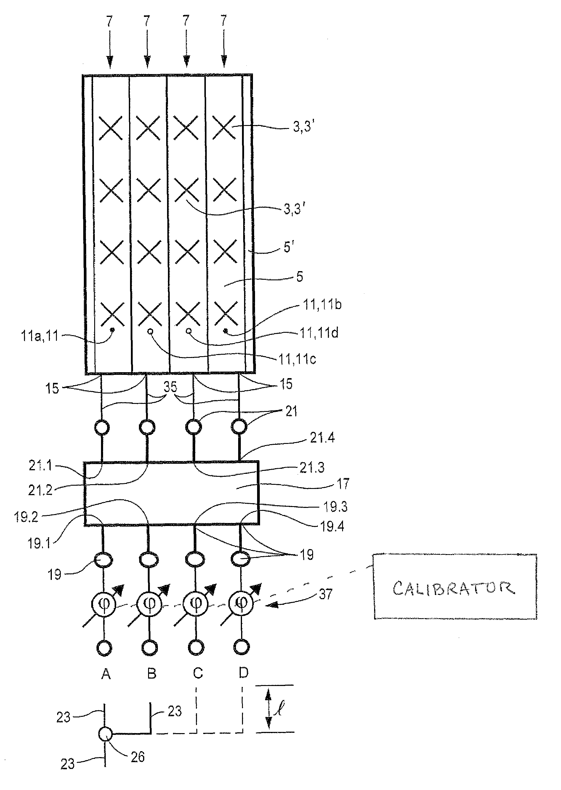
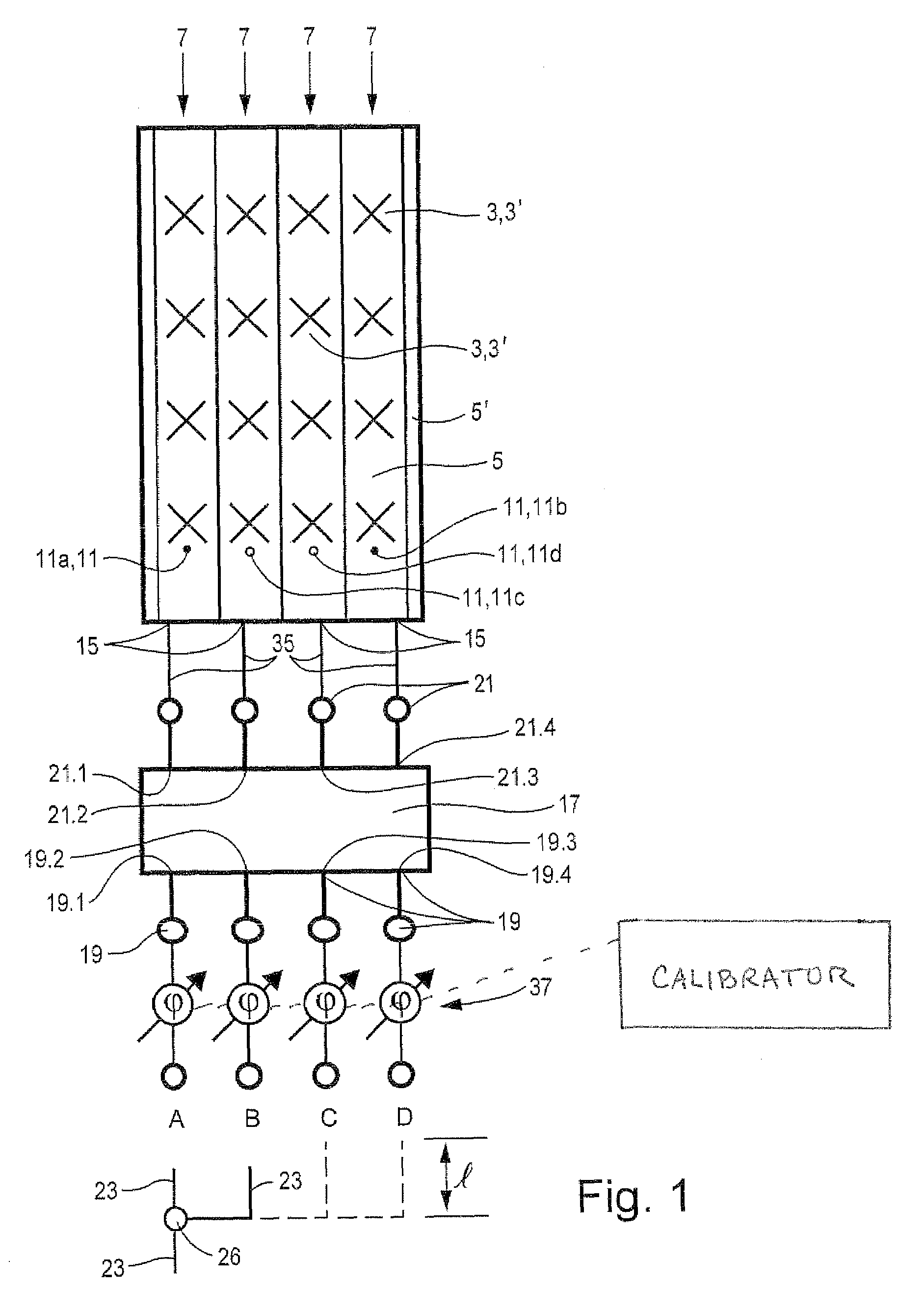
[0028]FIG. 1 shows a schematic plan view of an exemplary illustrative non-limiting implementation of an antenna array 1 which, for example, has a large number of dual-polarized antenna elements 3 arranged in front of a reflector 5. An edge boundary 5′, which belongs to the reflector, can be provided, for example, on the vertical longitudinal sides of the reflector 5 and is positioned at an angle of up to 90° with respect to the plane of the reflector plate. These reflector edge boundaries 5′ are often positioned such that they are inclined slightly outwards in the transmission direction.

[0029]In the illustrated exemplary implementation, the antenna array has four columns 7 which are arranged vertically, with four antenna elements or antenna element groups 3 being arranged one above the other in each column in the illustrated exemplary implementation.

[0030]Overall, four columns 7 are provided in the antenna array shown in FIGS. 1 and 2, in each of which the four antenna elements or a...


PUM


Abstract

A calibration device for a switchable antenna array, distinguished by the following improvements provides at least two inputs of two or more available inputs of the beam forming network fed simultaneously and/or jointly and/or in the same phase. The antenna elements have been trimmed in advance in order to produce intermediate lobes or further different azimuth beam directions, such that the individual lobes which are produced when at least two inputs are connected can be added with the correct phase.

Description

FIELD[0001]The technology herein relates to a switchable antenna array generally of the type including a Butler matrix type beam forming network, and more particularly to a calibration arrangement for such a beam forming network. The technology herein also relates to an associated operating method.BACKGROUND AND SUMMARY[0002]A known type of antenna array normally has two or more primary antenna elements arranged alongside one another and one above the other, resulting in a two-dimensional array arrangement. These antenna arrays, which are also known by the expression “smart antennas” are used, for example, in the military field for tracking targets (radar). However, recently, these antennas are also being increasingly used for mobile radio, in particular in the 800 MHz to 1000 MHz, and 1700 MHz to 2200 MHz frequency bands.[0003]The development of new primary antenna element systems has also made it possible to construct dual-polarized antenna arrays, in particular with a polarizatio...

Claims


Application Information

Patent Timeline
Patent Type & Authority Patents(United States)
IPC IPC(8): H01Q3/26G01R3/00H01Q3/40
CPCH01Q3/267H01Q3/40H01Q3/26H01Q3/22
Inventor LANGENBERG, JORG
Owner TELEFON AB LM ERICSSON (PUBL)
Why Eureka
Try Eureka