Engine combustion state detection device

a detection device and combustion state technology, applied in the direction of machines/engines, electric control, instruments, etc., can solve the problems of difficult differentiation between normal combustion states and abnormal combustion states, and reducing the detection accuracy of combustion states, etc., to achieve accurate detection of combustion states and high rotation range

Inactive Publication Date: 2006-11-07
DENSO CORP
View PDF13 Cites 41 Cited by
  • Summary
  • Abstract
  • Description
  • Claims
  • Application Information

AI Technical Summary

Benefits of technology

[0007]A main object of the present invention is to provide a combustion state detection device of an internal combustion engine that can accurately detect combustion states in a range containing a high rotation range of the internal combustion engine.
[0009]The rotation speed of the crankshaft fluctuates or varies according to combustion cycles of the internal combustion engine, and the rotation speed signal contains a frequency component (first frequency component) synchronized with combustion cycles. Moreover, the rotation speed signal contains the vibration (second frequency component) of the high-frequency component generated due to the torsion of the crankshaft or the like. It is confirmed that the second frequency component being the high-frequency component increases in rotation fluctuation particularly in a high rotation range of the internal combustion engine. Therefore, by using the second frequency component, engine combustion states can be accurately detected even in the high rotation range.
[0012]In a multi-cylinder internal combustion engine, the second frequency component is large in variations due to an attenuation characteristic among cylinders. The attenuation characteristic occurs depending on the rotation speed detection position of a crankshaft, and the arrangement of the cylinders. Cylinders more distant from the rotation speed detection position of the crankshaft experience more attenuation of rotation fluctuation of the high-frequency component. Accordingly, the rotation variation amount of the second frequency component is corrected on the basis of the attenuation characteristic of the second frequency component among the cylinders. By this operation, variations of the second frequency component among the cylinders can be eliminated.
[0013]By comparing a rotation variation amount of the second frequency component calculated for each cylinder and a rotation variation amount of the first frequency component, an attenuation learning value as the attenuation characteristic is calculated for each cylinder, and a rotation variation amount of the second frequency component is corrected by the attenuation learning value. In this case, if the rotation variation amount of the first frequency component is used as a reference value because it is small in variations among the cylinders, variations of rotation variation amounts of the second frequency component among the cylinders can be accurately learned.
[0014]Furthermore, when the internal combustion engine is in a specified low rotation state, an attenuation learning value may be calculated for each cylinder by the first frequency component and the second frequency component. Since variations of the first frequency component are particularly small in a low rotation state of the internal combustion engine, attenuation learning values can be accurately learned.
[0015]A rotation variation amount of the second frequency component may be corrected for each cylinder on the basis of cylinder-specific attenuation characteristic data of the second frequency component stored in advance. In this case, although attenuation characteristic data (e.g., map or the like) corresponding to the number of cylinders must be prepared, variations of the high-frequency component among the cylinders can be eliminated, and the detection accuracy of engine combustion states can be increased.

Problems solved by technology

However, according to the conventional detection method, as an engine speed increases, the detection accuracy of combustion states decreases.
Specifically, it is confirmed that the rotation speed fluctuation of each combustion cycle reduces in a high rotation range, and the reduced rotation speed fluctuation makes the differentiation between the normal combustion state and the abnormal combustion state difficult, causing reduction in the detection accuracy of combustion states.

Method used


Image

  • Engine combustion state detection device
  • Engine combustion state detection device
  • Engine combustion state detection device

Examples


Embodiment Construction

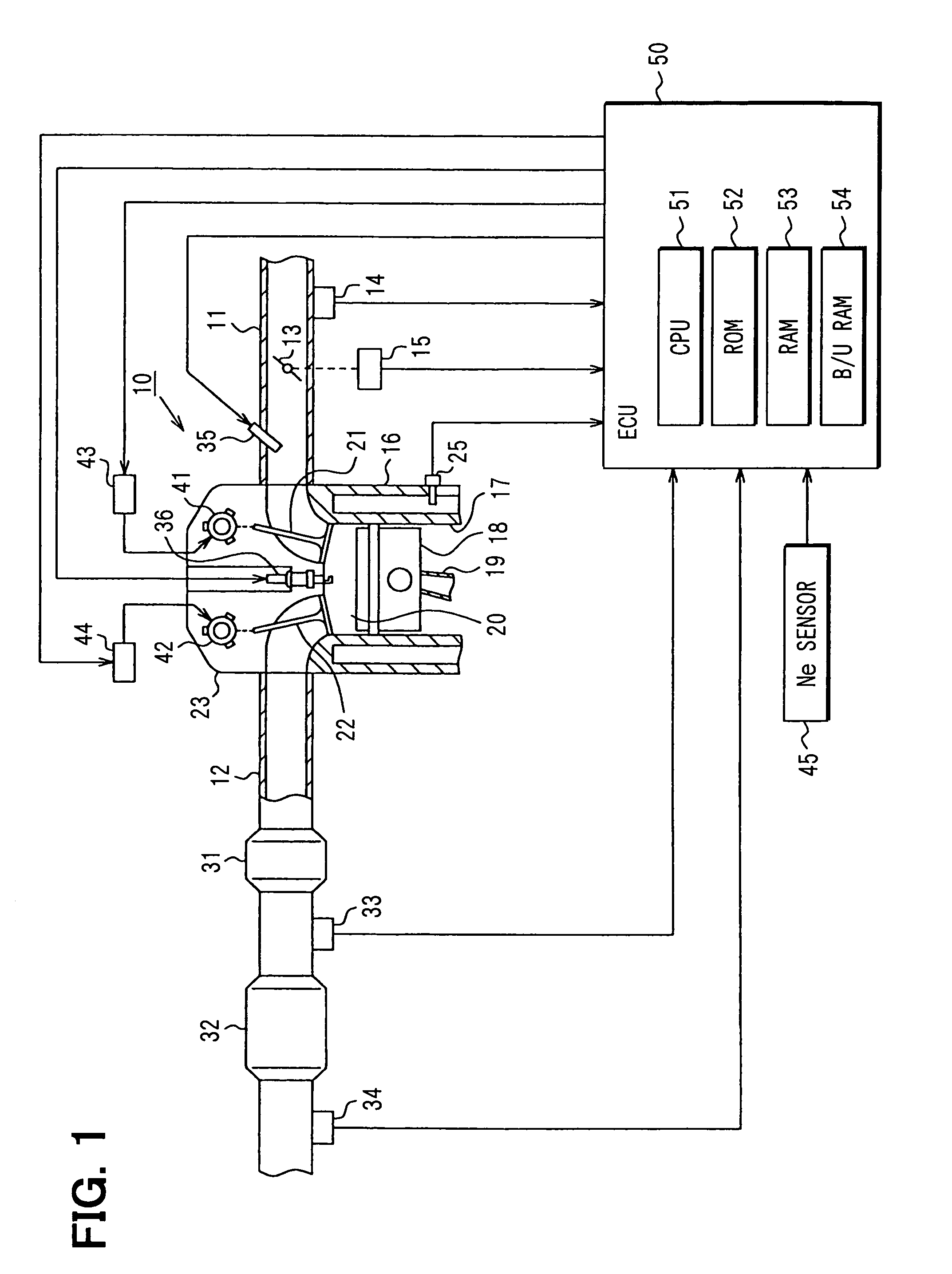
[0035]In FIG. 1 showing an embodiment, an engine control system is for a four-cycle multi-cylinder internal combustion engine 10 of spark-ignition type. In the control system, an electronic control unit (ECU) 50 controls fuel injection quantities and ignition timing.

[0036]The engine 10 has an intake pipe 11 and an exhaust pipe 12, which are connected to intake ports and exhaust ports, respectively. The intake pipe 11 is provided with a throttle valve 13 linked to an accelerator pedal, and disposed with an air flow meter 14 for detecting the quantity of intake air. The degree of opening of the throttle valve 13 is detected by a throttle sensor 15. The full closing of the throttle can also be detected by the sensor 15.

[0037]A cylinder 17 is formed in a cylinder block 16, and a piston 18 is disposed within the cylinder 17. The piston 18 is coupled to a crankshaft (not shown) through a connecting rod 19. A combustion chamber 20 partitioned by the cylinder block 16 and a cylinder head 23...


PUM


Abstract

A rotation angle sensor detects the rotation speed of a crankshaft of an engine. An ECU extracts a first frequency component synchronized with combustion cycles of the engine that is contained in a rotation speed signal obtained by the detection of the rotation angle sensor, and a second frequency component having a higher frequency than the first frequency component. It detects a combustion state by using the rotation variation amount of the first frequency component in a lower rotation range than a specified engine speed, and by using the rotation variation amount of the second frequency component in a higher rotation range.

Description

CROSS REFERENCE TO RELATED APPLICATION[0001]This application is based on and incorporates herein by reference Japanese patent application No. 2004-63328 filed on Mar. 8, 2004.FIELD OF THE INVENTION[0002]The present invention relates to a device for detecting combustion states of an internal combustion engine.BACKGROUND OF THE INVENTION[0003]It is known that, during the operation of an internal combustion engine, the rotation speed of the internal combustion engine fluctuates according to combustion cycles. Some conventional technologies detect a combustion state such as misfire on the basis of combustion cycle fluctuation of the rotation speed.[0004]For example, according to U.S. Pat. No. 6,401,527, a combustion state is detected by comparing a rotation variation amount in the former half of one combustion cycle and a rotation variation amount in the latter half.[0005]According to JP-2000-240500A, in the normal operation state, angular speed fluctuation difference amounts of a crank...

Claims


Application Information

Patent Timeline
Patent Type & Authority Patents(United States)
IPC IPC(8): F02P5/152F02D41/00F02D45/00G01M15/00
CPCF02D35/024F02D35/028G01M15/046F02D41/1498F02D2041/288F02D2200/101F02D2200/1012
Inventor KOKUBO, NAOKI
Owner DENSO CORP
Why Eureka
Try Eureka