Integral restraint system and method of manufacture for plastic pipe

a technology of plastic pipe and restraint system, which is applied in the field of self-restraining sealing system and dual function, can solve the problems of cumbersome substantial additional effort, and inconvenient installation of restraint system, so as to reduce the chance of human error, simplify the installation of pipe sections, and reduce the effect of labor intensity

Active Publication Date: 2006-11-14
S & B TECHN PRODS
View PDF13 Cites 33 Cited by
  • Summary
  • Abstract
  • Description
  • Claims
  • Application Information

AI Technical Summary

Benefits of technology

[0011]It is a preferred object of the invention to provide an improved restraint system for plastic pipe joints utilizing the “gasket formed” bell groove, which does not require assembly in the field and which thus simplifies installation of pipe sections at the pipe joints used to form a fluid conveying pipeline, thereby reducing the chance of human error or of damage or contamination of the gasket sealing surfaces.
[0012]Another object is to eliminate the need for an external clamping device of the type presently used in the industry to achieve the restraining function, which device is totally separated from the sealing function.
[0013]Another object of the present invention is to provide an improved restraint system for plastic pipe which is simple in design and dependable in operation and which is less costly than the restraining systems presently employing external mechanical restraints.
[0014]In the method and apparatus of the invention, an integral bell pipe-to-pipe restraint system is provided for restraining pipe against internal forces at a pipe coupling or fitting connection and for joining and sealing at least two pipes to form a pipeline. The restraint system of the invention utilizes an elastomeric sealing ring in conjunction with some type of cooperating restraint mechanism. The restraint mechanism may be integral with the sealing ring or may be a separate ring. In some cases the restraint mechanism may be individual segments with teeth. In other cases, the restraint mechanism is a single solid ring with one slit in the periphery. The female end of the plastic pipe is preferably belled around the restraining and sealing mechanism so that the restraint system is integral with the bell. In this way, it is not necessary to install the restraint system in the field and, since the system is also locked in position at the factory by means of the belling operation, it is less likely to be dislodged or twisted during assembly of the pipe joint.
[0019]The restraining mechanism preferably includes a sealing member with an elastomeric body and a gripper member. The gripper member can be at least partly contained within the elastomeric body of a sealing member or the restraining mechanism can comprise an elastomeric sealing ring and a separate relatively rigid gripper ring located within the groove provided in the belled end opening of the female pipe. In one preferred embodiment of the method of the invention, the sealing ring is intentionally provided with an excess of elastomeric material over and above that which would be necessary for establishing a seal under existing pressure conditions with a mating male pipe to form a pipe coupling, the excess material serving to energize the action of the separate gripper ring in engaging an external surface of the male pipe.

Problems solved by technology

Most current restraining systems offered in the industry require a substantial amount of labor to install.
Under most installation conditions, the restraining systems are cumbersome to install and represent a substantial additional effort for the contractor.
As a result, these and other traditional restraining mechanisms of the prior art add considerable cost and complexity to the pipe installation as well as adding the possibility of human error depending upon the specific field conditions and applications.

Method used


Image

  • Integral restraint system and method of manufacture for plastic pipe
  • Integral restraint system and method of manufacture for plastic pipe
  • Integral restraint system and method of manufacture for plastic pipe

Examples


Embodiment Construction

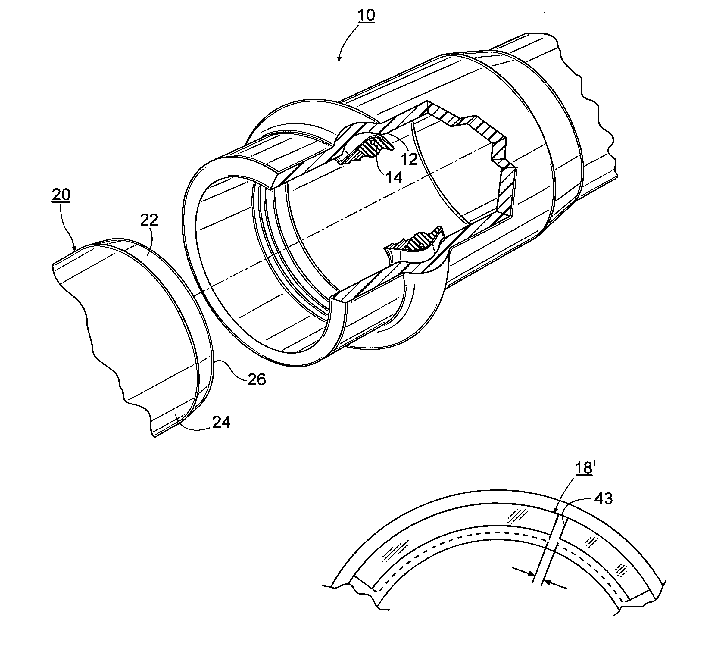
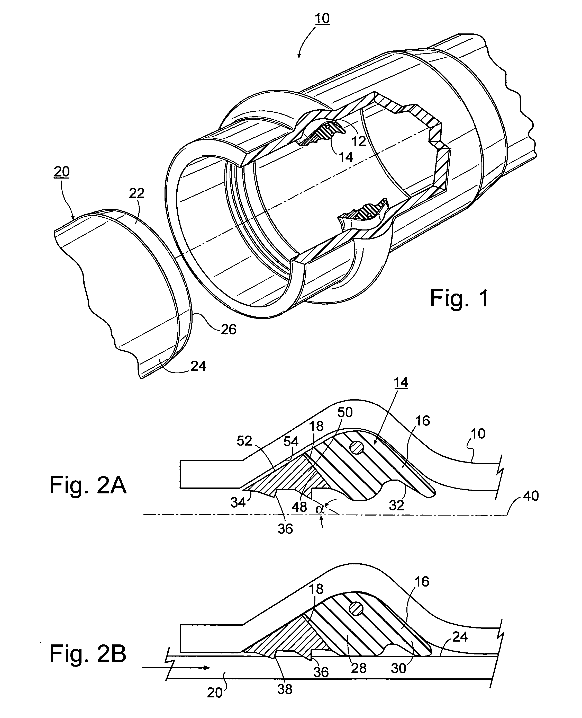
[0032]Turning to FIG. 1, there is shown an exploded view of a plastic pipe joint in which a belled female pipe end 10 is provided with an annular groove 12 for receiving the restraining mechanism 14 of the invention. As best seen in FIGS. 1, 2A and 2B, the restraining mechanism 14 includes an elastomeric, circumferential sealing portion 16 and a relatively rigid, segmented annular gripper ring portion 18. The improved integral restraining mechanism of the invention is capable of joining and sealing the female plastic pipe 10 to a mating male plastic pipe section 20 having a spigot end 22 and having an exterior surface 24 and an interior surface 26. The plastic pipe male and female ends 10, 20 can be made from any convenient synthetic material including the polyolefins such as polyethylene and polypropylene but is preferably made from polyvinyl chloride (PVC).

[0033]As will be apparent from the description which follows, the present manufacturing process uses a variation of the so-cal...


PUM

PropertyMeasurementUnit
angleaaaaaaaaaa
diameteraaaaaaaaaa
pressureaaaaaaaaaa

Abstract

A method and apparatus for restraining pipe against internal forces at a pipe or fitting connection and to join and seal at least two pipes to form a pipeline is shown featuring an improved restraining / sealing mechanism. The restraining / sealing mechanism includes a relatively rigid gripper ring and a companion sealing ring which are received within one or more mating grooves provided in the belled end of a female pipe. The gripper ring and sealing ring can be combined or attached, or they can be separate members located in the same retaining groove or separate grooves in the female belled pipe end.

Description

CROSS-REFERENCE TO RELATED APPLICATIONS[0001]The present application claims priority from the following U.S. Provisional Applications: Ser. No. 60 / 498,194, filed Aug. 25, 2003, entitled “Restrained Ring Joint For Plastic Pipe”, by Bradford G. Corbett, Jr.; Ser. No. 60 / 501,508, filed Sep. 9, 2003, entitled “Reiber Style Self Restraining Gasket For Plastic Pipe”, by Bradford G. Corbett, Jr.; Ser. No. 60 / 506,073, filed Sep. 24, 2003, entitled “Rieber Style Self Restraining Gasket For Plastic Pipe”, by Bradford G. Corbett, Jr. and Jim Jones; and Ser. No. 60 / 506,791, filed Sep. 29, 2003, entitled “Integral Bell Pipe-to Pipe Restraint System For Plastic Pipe”, by Bradford G. Corbett, Jr. and Jim Jones.BACKGROUND OF THE INVENTION[0002]1. Field of the Invention[0003]The present invention relates generally to the field of pipe connections, and in particular, to a dual function, self restraining sealing system that is used to form a secure pipe connection between two plastic pipes and to a me...

Claims


Application Information

Patent Timeline
Patent Type & Authority Patents(United States)
IPC IPC(8): B21D51/16F16L37/084F16L37/092
CPCF16L37/0845F16L37/0925F16L47/12F16L47/08Y10T29/49865Y10T29/49428
Inventor CORBETT, JR., BRADFORD G.JONES, JIM
Owner S & B TECHN PRODS
Why Eureka
Try Eureka