Driving force distribution apparatus for right and left wheels

a technology of driving force distribution and right and left wheels, which is applied in the direction of fluid couplings, gearings, couplings, etc., can solve the problems of increasing complexity and size of the right and left axle apparatus, difficulty in mounting the driving force distribution apparatus on the vehicle, and oil leakag

Inactive Publication Date: 2006-11-14
SUBARU CORP
View PDF5 Cites 3 Cited by
  • Summary
  • Abstract
  • Description
  • Claims
  • Application Information

AI Technical Summary

Benefits of technology

[0008]The present invention has been achieved in view of the foregoing problems. It is thus an object of the present invention to provide a driving force distribution apparatus capable of applying relative rotating forces to right and left axles even when a vehicle is running backward, without increasing a size of the entire apparatus.
[0010]According to the present invention, the swash plate is supported so as to be able to tilt to one side and the other side freely. When the shaft rotates in the forward direction or in the reverse direction, the swash plate and the cylinder unit make relative rotations so that the pistons are reciprocated inside the cylinder holes via the tilt surface. This makes the hydraulic oil sucked from the tank flow into the channel which leads to the predetermined suction port of the operation control valve. Consequently, the hydraulic pump sucks the hydraulic oil from an oil channel, and flows the hydraulic oil into the pump oil channel leading to the suction port of the operation control valve irrespective of the direction of the rotation of the pump shaft. Suppose here that the oil channel for supplying the hydraulic oil from the operation control valve to the hydraulic motor is designed for higher pressures, and the oil channel for establishing connection between the tank and the hydraulic pump is designed for lower pressures. Even in this case, the hydraulic oil sucked from the tank flows through the pump oil channel and the operation control valve into the high-pressure oil channel for pressurization, which prevents cavitation from occurring in the oil channel leading to the hydraulic motor. This can avoid the situation where the hydraulic oil leaks from the oil channel or the like due to the occurrence of the cavitation. Moreover, even when the vehicle runs backward, the hydraulic oil can be supplied to the hydraulic motor without causing the cavitation. It is therefore possible to apply relative rotating forces to the right and left axles with stability while the vehicle is running backward.
[0012]According to the distribution apparatus of the present invention, it is possible to apply relative rotating forces to the left and right axles even when the vehicle runs backward, without increasing the size of the entire apparatus.

Problems solved by technology

Oil leakage can also occur.
This can produce the problem, however, that the driving force distribution apparatus for right and left the axles is increased in complexity and in size, making it difficult to mount the driving force distribution apparatus on the vehicle.

Method used


Image

  • Driving force distribution apparatus for right and left wheels
  • Driving force distribution apparatus for right and left wheels
  • Driving force distribution apparatus for right and left wheels

Examples


Embodiment Construction

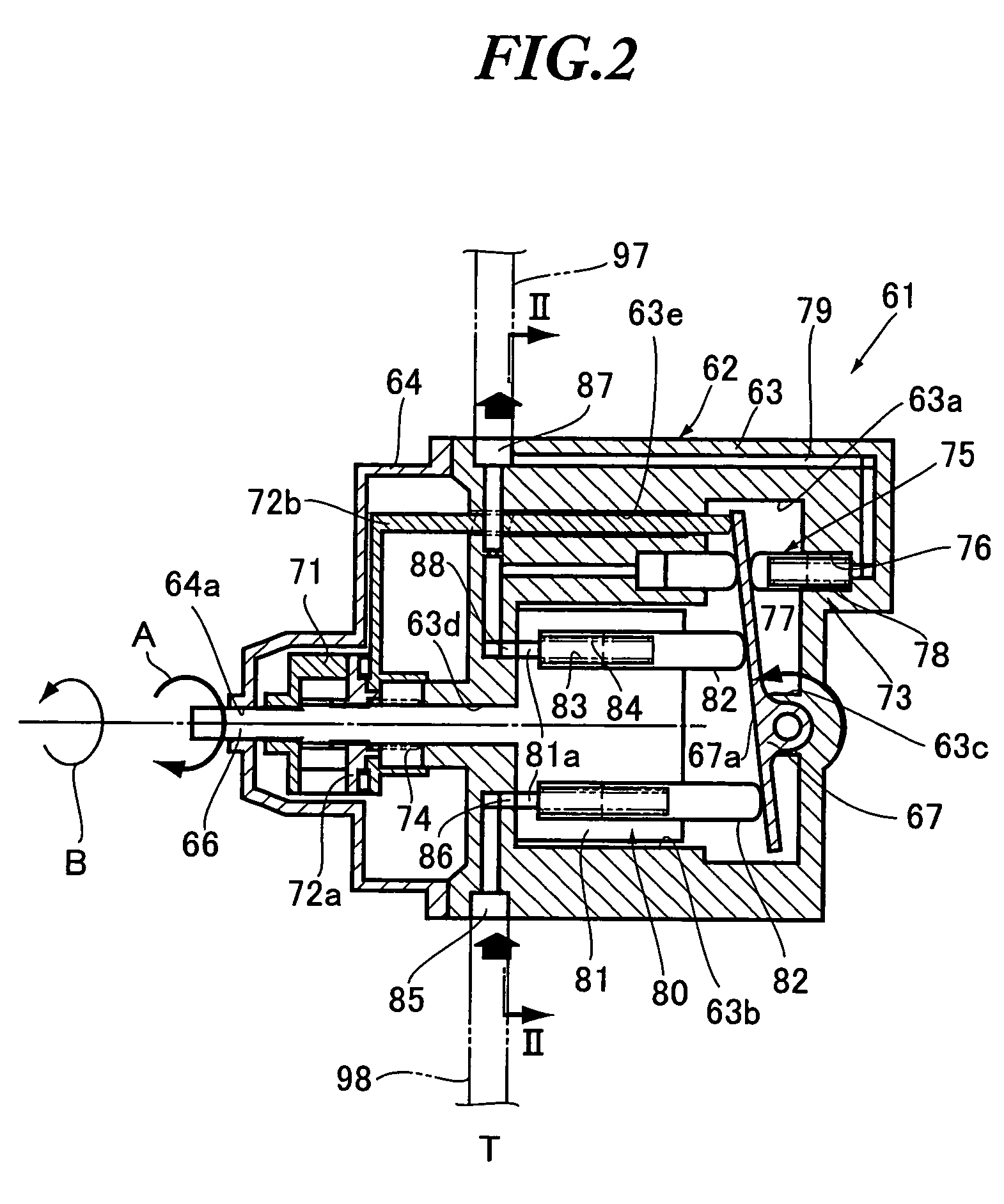
[0020]Hereinafter, a preferred embodiment of a driving force distribution apparatus for right and left axles according to the present invention will be described with reference to FIGS. 1 to 5. The present embodiment will be explained by an example of the driving force distribution apparatus which is connected to the axles of a pair of rear wheels arranged on both right and left sides of a vehicle such as an automobile.

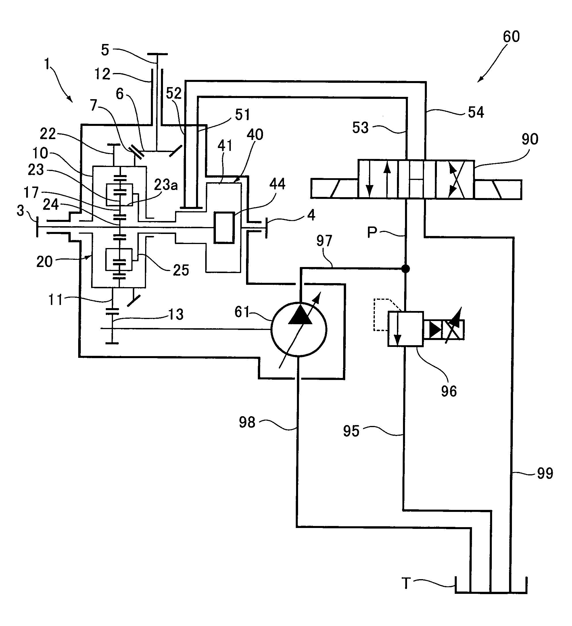
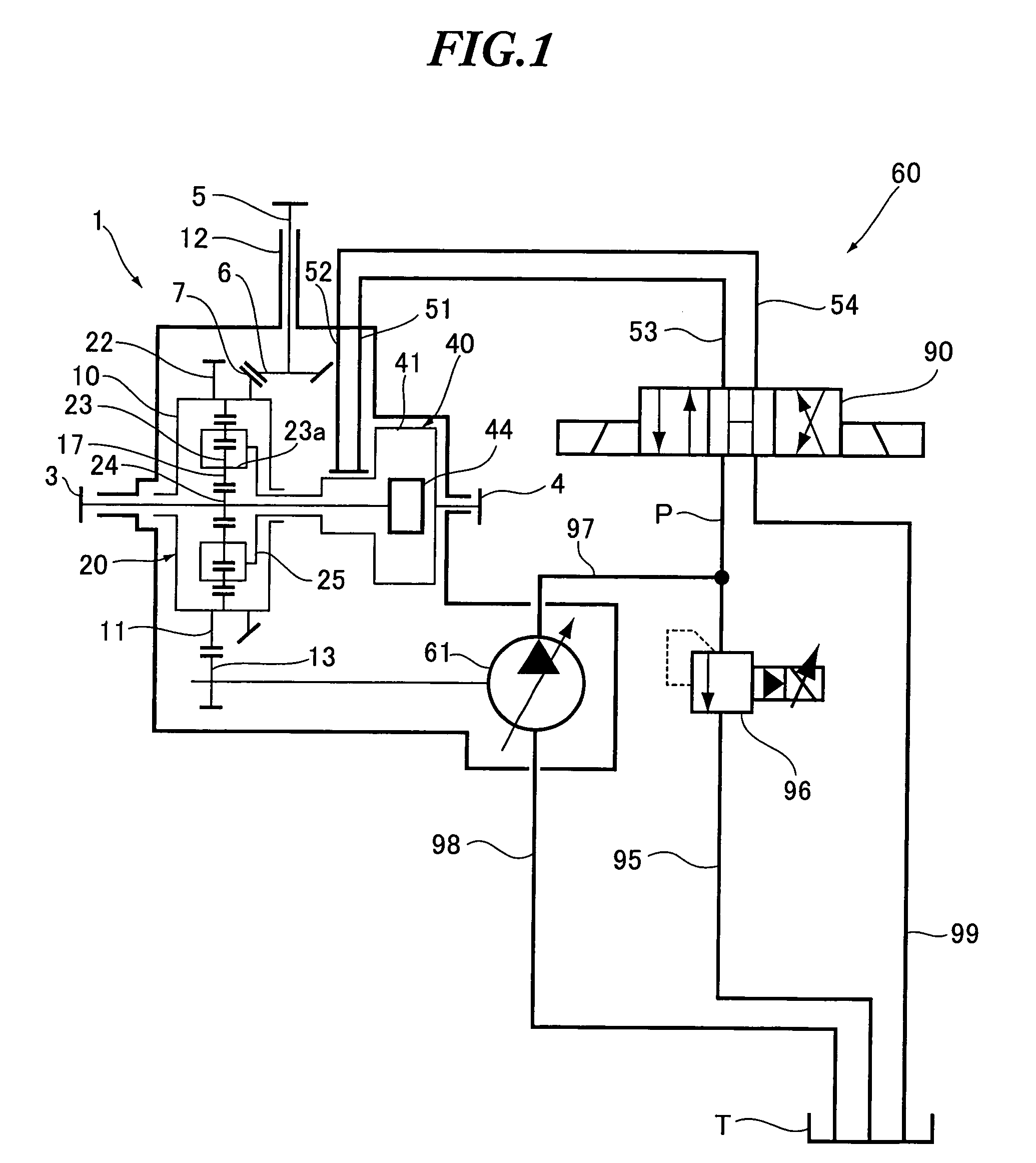
[0021]As shown in FIG. 1 (sectional view), the driving force distribution apparatus 1 comprises a differential unit 20, a hydraulic motor 40, and a hydraulic mechanism 60. The differential unit 20 includes a planetary gear mechanism for distributing and transmitting a driving force transmitted from an engine to left and right axles 3 and 4. The hydraulic motor 40 applies relative rotating forces to the left and right axles 3 and 4. The hydraulic mechanism 60 controls a supply and exhaust of hydraulic oil discharged from a hydraulic pump 61 to the hydraulic motor 40 by...


PUM


Abstract

A hydraulic pump of a driving force distribution apparatus for right and left axles includes a pump shaft, a swash plate supported tiltably, swash plate tilting and holding mechanism unit for tilting and holding the swash plate to one side or to the other side depending on the direction of rotation of the pump shaft, and a hydraulic oil supply mechanism unit having a cylinder block. The cylinder block holds pistons which reciprocate inside cylinder holes while making contact with a tilt surface of the swash plate at their extremities. When the pump shaft rotates in a forward or reverse direction, the pistons reciprocate to supply hydraulic oil sucked from a tank to a suction port of an operation control valve. Thus, the driving force distribution apparatus can apply relative rotating forces to right and left axles even during backward running, with no increase in the size of the apparatus.

Description

BACKGROUND OF THE INVENTION[0001]The present invention relates to a driving force distribution apparatus for distributing driving forces to be transmitted to right and left wheels.[0002]The present application claims priority from Japanese Patent Application No. 2004-096185, the disclosure of which is incorporated herein by reference.[0003]Among such driving force distribution apparatuses is one comprising a differential case, a differential unit, a hydraulic motor, and a hydraulic pump (see Japanese Patent Application Laid-Open No. 2003-130175). Here, a rotational driving force of a propeller shaft which is rotatably supported and connected to an engine side thereof is transmitted to the differential case through gears. The differential unit distributes and transmits an input driving force to the differential case to right and left axles by using a planetary gear mechanism. The hydraulic motor gives relative rotating forces to the right and left axles. The hydraulic pump drives the...

Claims


Application Information

Patent Timeline
Patent Type & Authority Patents(United States)
IPC IPC(8): F16D31/02F16H48/20B60K17/10F16H48/06F16H39/02F16H47/04F16H48/18F16H48/26F16H48/27F16H48/38
CPCB60K17/105F16D31/02F16H47/04F16H48/10F16H48/16F16H48/30F16H48/34F16H61/438F16H61/46F16H61/472F16H48/26F16H48/32F16H2048/204F16H2048/423F16H2200/2071
Inventor TANAKA, TAKASHI
Owner SUBARU CORP
Why Eureka
Try Eureka