Apparatus for chipping material

Active Publication Date: 2006-11-14
PALLMANN MASCHFAB GMBH & CO KG
View PDF4 Cites 5 Cited by
  • Summary
  • Abstract
  • Description
  • Claims
  • Application Information

AI Technical Summary

Benefits of technology

[0015]A first advantage of the invention is the automatic indication of an attrition border. An operator of a device of this invention no longer has to take the initiative to determine the state of attrition of the chipping tools. Rather, the need to change out the tools is signaled to the operator by the appearance of apertures in the surface of the chipping tools. The apertures, which appear in the otherwise evenly structured surface of the chipping tools when the attrition border is reached, are easily visible and thus hard to miss so that very good recognition is guaranteed, which improves the operational safety for the operator.
[0016]A further advantage of the invention is the option to place an arbitrary number of bores at arbitrary locations. This makes it possible to monitor the state of attrition not only at the edges of the chipping tools, but also, for example, in the middle of the surface. This also allows an indication of the state of attrition when uneven wear and tear across the surface of the chipping tool occurs.
[0017]In a further advantageous embodiment of this invention, the bores, at their lowest point, taper to a point, that is, the bores terminate, pointed, in the division plane between the core area and the utilization area. When attrition takes places beyond the utilization area, inevitably an enlargement of the apertures takes place. In this way, the urgency of a tool change can be determined from the size of the apertures.
[0018]Preferred are bores that have a constant cross-section, whereby the depth can be varied. Such a bore can be formed in a simple way with a bore having a cone-shaped borehole.
[0019]In a further advantageous embodiment of the invention, the bores are made with drills having an internal screw thread. This allows the fastening of the chipping tools with screws, which, extending from the carrier elements, engage with the bores made by drills with internal screw threads. This gives the bores a double function, namely, the fastening of the chipping tools and the indication of the state of attrition of the chipping tools.
[0020]In a particularly beneficial embodiment of the invention is an arrangement, whereby the bores are spaced from the outer edge of the chipping tools in intervals of 5% of the total diameter of the chipping tools. In this way, at least the state of attrition of those areas of the chipping tools, which are exposed to heavier wear and tear, is being monitored. In order to maintain minimum control over the overall state of attrition of the chipping tools, at least three equally spaced bores are provided, that is, three bores are provided at an angular distance of 120° to the axis of rotation. By increasing the number of bores, the angular distance is decreased proportionally.

Problems solved by technology

The material is hurled against the profiled surface of the chipping tools, where it is broken up and crushed.
This results in natural wear of the chipping tools so that the worn-down chipping tools have to be replaced at regular time intervals.
However, each time reconditioning takes place the thickness of the chipping tools decreases.
Thus, reconditioning cannot be repeated interminably, rather, for static reasons, it must stop when the gradual weakening of the chipping tool cross-section has progressed to a point where the chipping tools are no longer able to withstand the mechanical stress during the chipping process.
Therefore, the danger of using a chipping tool beyond its utilization area is that the chipping tool can no longer withstand the heavy mechanical stress and will be destroyed.
The fragments resulting therefrom can lead to serious damage to the entire chipping apparatus.
This way of determining the state of attrition is relatively labor intensive, so that in the work place this procedure is often not done at all or not often enough.
Moreover, the disadvantage of this procedure is that there is no automatic indicator of the state of attrition, that is, the operator of such a chipping apparatus has to check the state of attrition on his / her own initiative.
The disadvantage of markings is that if put on the surface of the chipping tool, they can be erased by mechanical use and thus become invisible.
When using stamps there is the danger that dirt deposits, which accumulate in the stamps over time, will make them hard to recognize.
Both procedures have the disadvantage that an examination of the state of the chipping tools can only take place at their edges.
With uneven wear and tear, getting below the static minimum thickness in the middle of the surface remains undetected.

Method used


Image

  • Apparatus for chipping material
  • Apparatus for chipping material
  • Apparatus for chipping material

Examples


Embodiment Construction

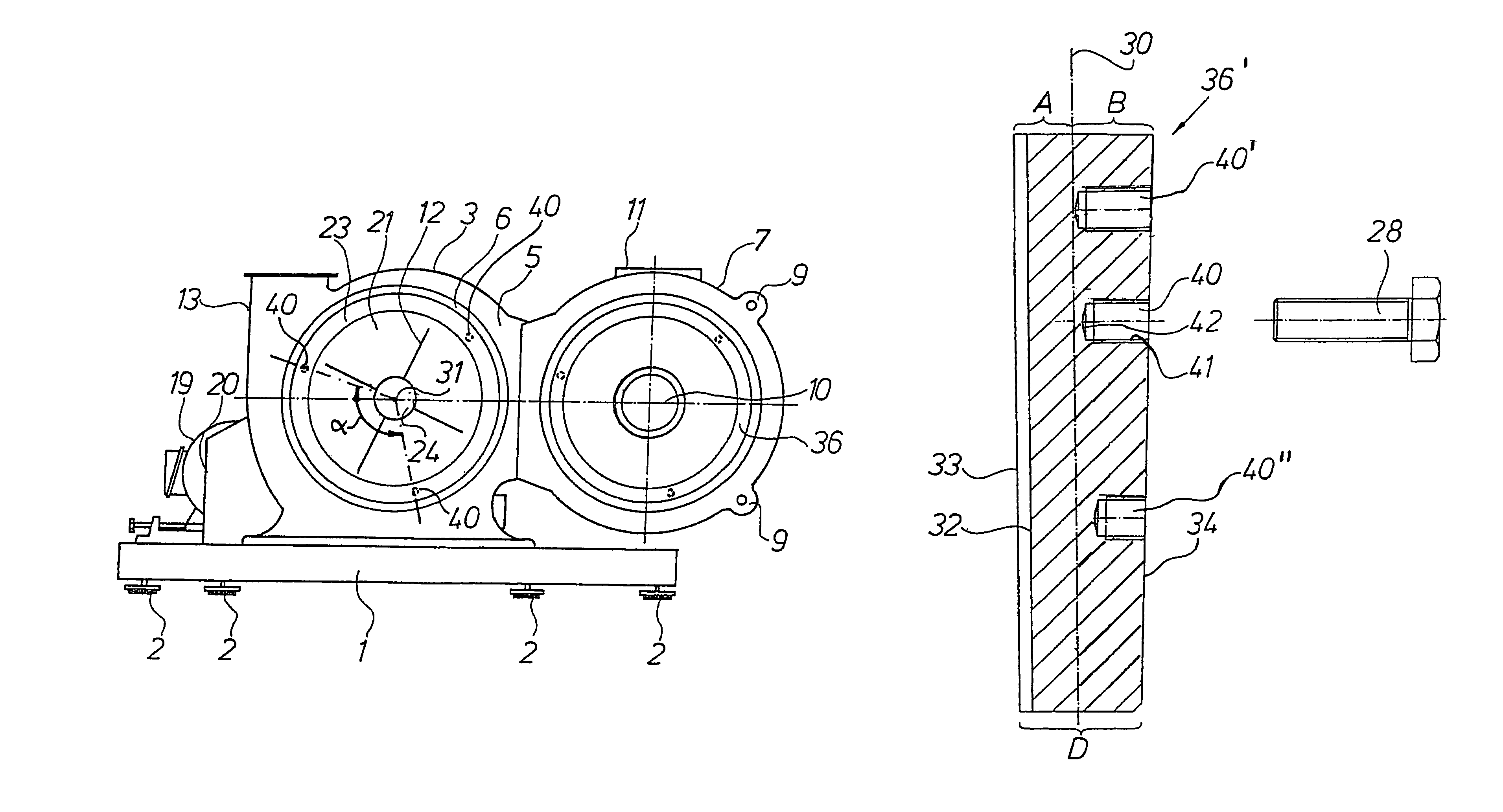
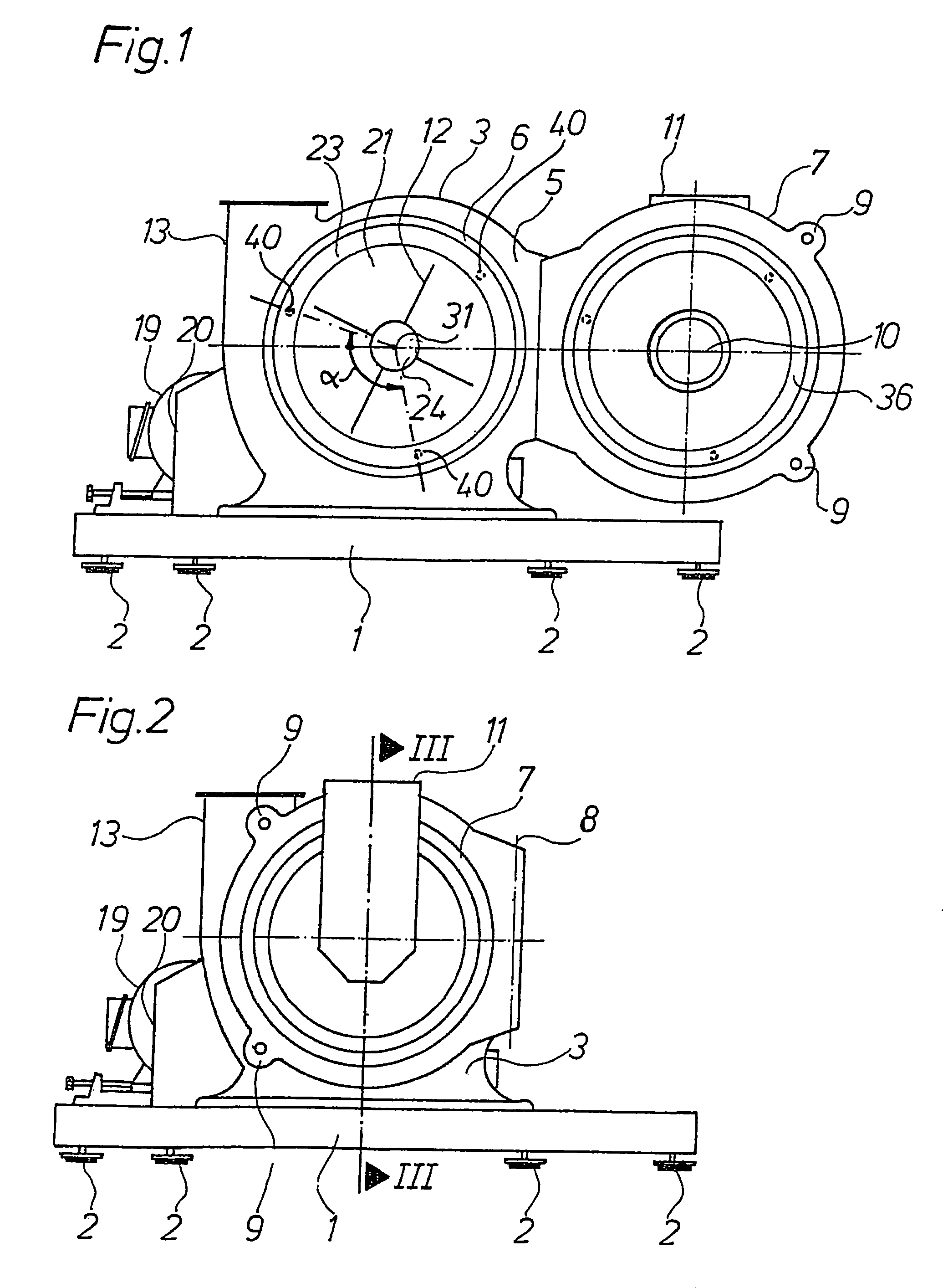
[0030]In FIGS. 1, 2, and 3, the essential elements of an apparatus of this invention are illustrated. In FIGS. 1 and 2, which are front views showing a housing door 7 opened and closed, respectively, and an apparatus substructure 1 having its feet 2 on a solid base. The upper part of the apparatus substructure 1 forms a platform, onto which a chipping device according to the present invention is mounted.

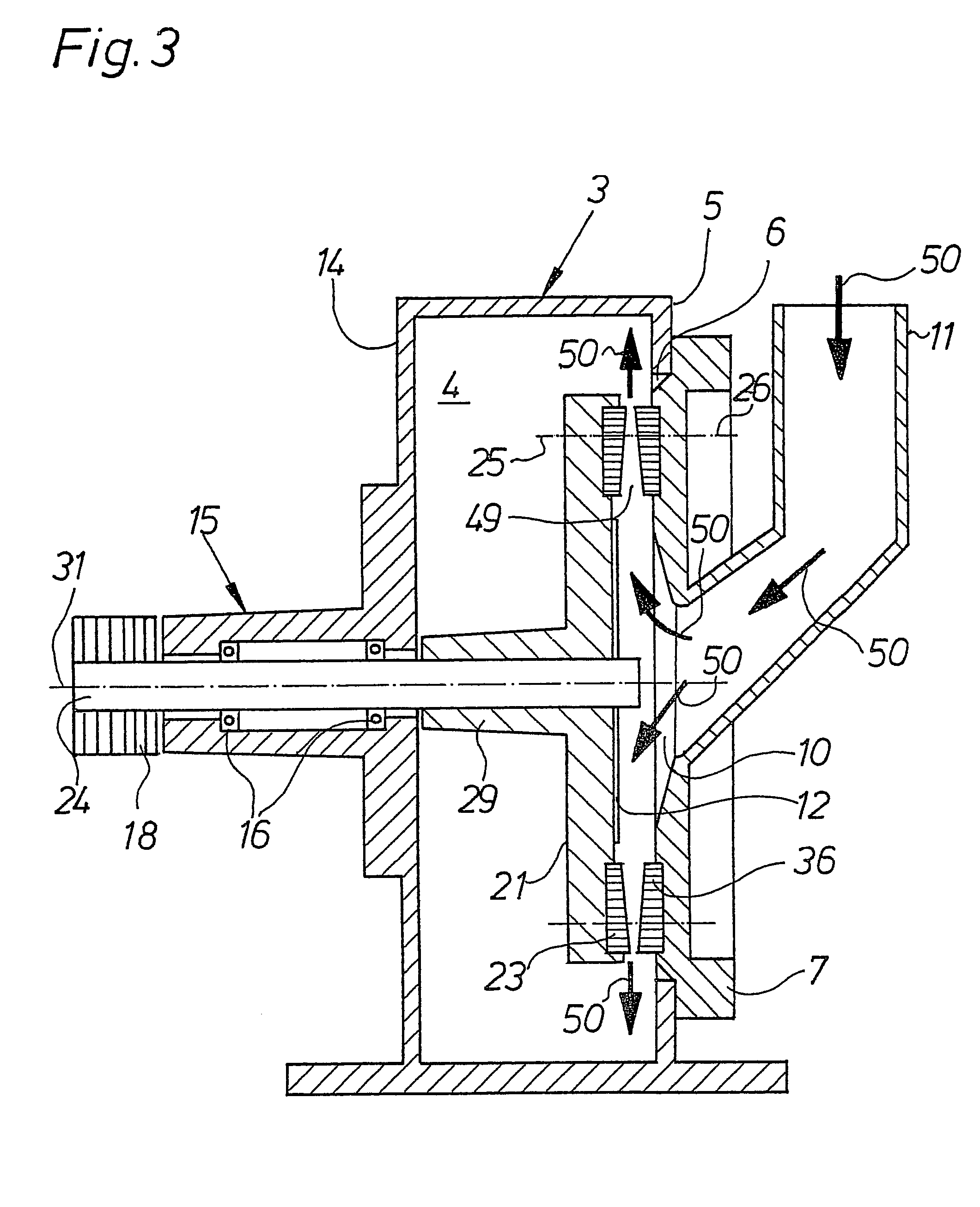
[0031]The chipping device includes a drum-shaped housing 3 that encloses a chipping chamber 4. On its front wall 5, the housing 3 has a central circular opening 6, which can be closed by using a housing door 7 that pivots about a vertical axis 8 and can be locked with locks 9.

[0032]The housing door 7 is also equipped with a central input opening 10, to which a fall shaft 11 is attached, which extends vertically from the outside and, at a slant angle in the bottom area, connects to the input opening 10. The input opening 10 expands conically across the thickness of housing door 7 towa...


PUM


Abstract

An apparatus and a tool for chipping material are provided. The apparatus includes chipping tools arranged relative to one another inside a housing, whereby the chipping tools are constructed planiformly, and are arranged on carrier elements along a drum-shaped, disk-shaped, or ring-shaped chipping path. The chipping tools rotate relative to one another by rotating about an axis of rotation, and are each divided by a division line based on their thickness into a core area, which faces the carrier element, and a utilization area, which is positioned opposite of the chipping tools. The chipping tools have at least one bore, formed perpendicular to the division line, the bore extends across the utilization area and ends at the division line between the core area and the utilization area. In this way, an automatic indication of a critical state of attrition is accomplished, when from a static viewpoint damage to or destruction of the chipping tool as a result of mechanical stress during the operation of the apparatus can be expected.

Description

[0001]This non-provisional application claims priority under 35 U.S.C. § 119(a) on German Patent application No. 202 16 056.4, filed in Germany on Oct. 18, 2002, which is herein incorporated by reference.BACKGROUND OF THE INVENTION[0002]1. Field of the Invention[0003]This invention relates to a chipping apparatus for materials and a disk-shaped chipping element.[0004]2. Description of the Background Art[0005]Conventional chipping devices in this class are known, for example, as disk mills, refiners, beater mills, or cone mills. In these chipping devices, the dumpable material is fed axially into the center of the chipping chamber, which is enclosed by the housing, and is then diverted into a radial direction, where chipping tools rotating around a central axis of rotation take hold of and chip the material.[0006]The chipping tools are located inside the housing relative to one another at an axial or radial distance, and thus form a rotation-symmetrical milling gap where the chipping...

Claims


Application Information

Patent Timeline
IPC IPC(8): B27C1/00B02C7/06B02C7/12
CPCB02C7/06B02C7/12Y10T407/1946B02C2210/01
Inventor PALLMANN, HARTMUT
Owner PALLMANN MASCHFAB GMBH & CO KG
Why Eureka
Try Eureka