Investment casting cores and methods

a technology of investment casting and cores, applied in the field of investment casting, can solve the problems of difficult manufacturing, limited hole shapes produced by such edm techniques, and associated cost in engine efficiency

Active Publication Date: 2006-11-14
RTX CORP
View PDF18 Cites 53 Cited by
  • Summary
  • Abstract
  • Description
  • Claims
  • Application Information

AI Technical Summary

Benefits of technology

[0011]Various implementations involve forming the first core element from sheet stock having opposite first and second faces. The at least one recess may include a first recess in the first face and a second aligned recess in the second face. The first and second recesses may be elongate channels. The engaging may involve translating a first portion of the first core into a slot in the mating one so that a projecting portion of the mating one within the slot is received into the at least one recess so as to provide a mechanical back-locking effect. The forming may involve forming a regular pattern of recesses including the at least one recess. The engaging may leave exposed a number of the recesses of the regular pattern. The regular pattern may be pre-formed in flat sheet stock. The metallic first core element may be cut and / or shaped from such sheet stock.

Problems solved by technology

Such cooling comes with an associated cost in engine efficiency.
The cores defining fine features may be difficult to manufacture and / or, once manufactured, may prove fragile.
The hole shapes produced by such EDM techniques are limited by electrode insertion constraints.
As is the case with the use of multiple ceramic cores, assembling the ceramic and refractory metal cores and maintaining their spatial relationship during wax overmolding presents numerous difficulties.
A failure to maintain such relationship can produce potentially unsatisfactory part internal features.
It may be difficult to assemble fine refractory metal cores to ceramic cores.
Once assembled, it may be difficult to maintain alignment.
The refractory metal cores may become damaged during handling or during assembly of the overmolding die.
Assuring proper die assembly and release of the injected pattern may require die complexity (e.g., a large number of separate die parts and separate pull directions to accommodate the various RMCs).

Method used


Image

  • Investment casting cores and methods
  • Investment casting cores and methods
  • Investment casting cores and methods

Examples


Embodiment Construction

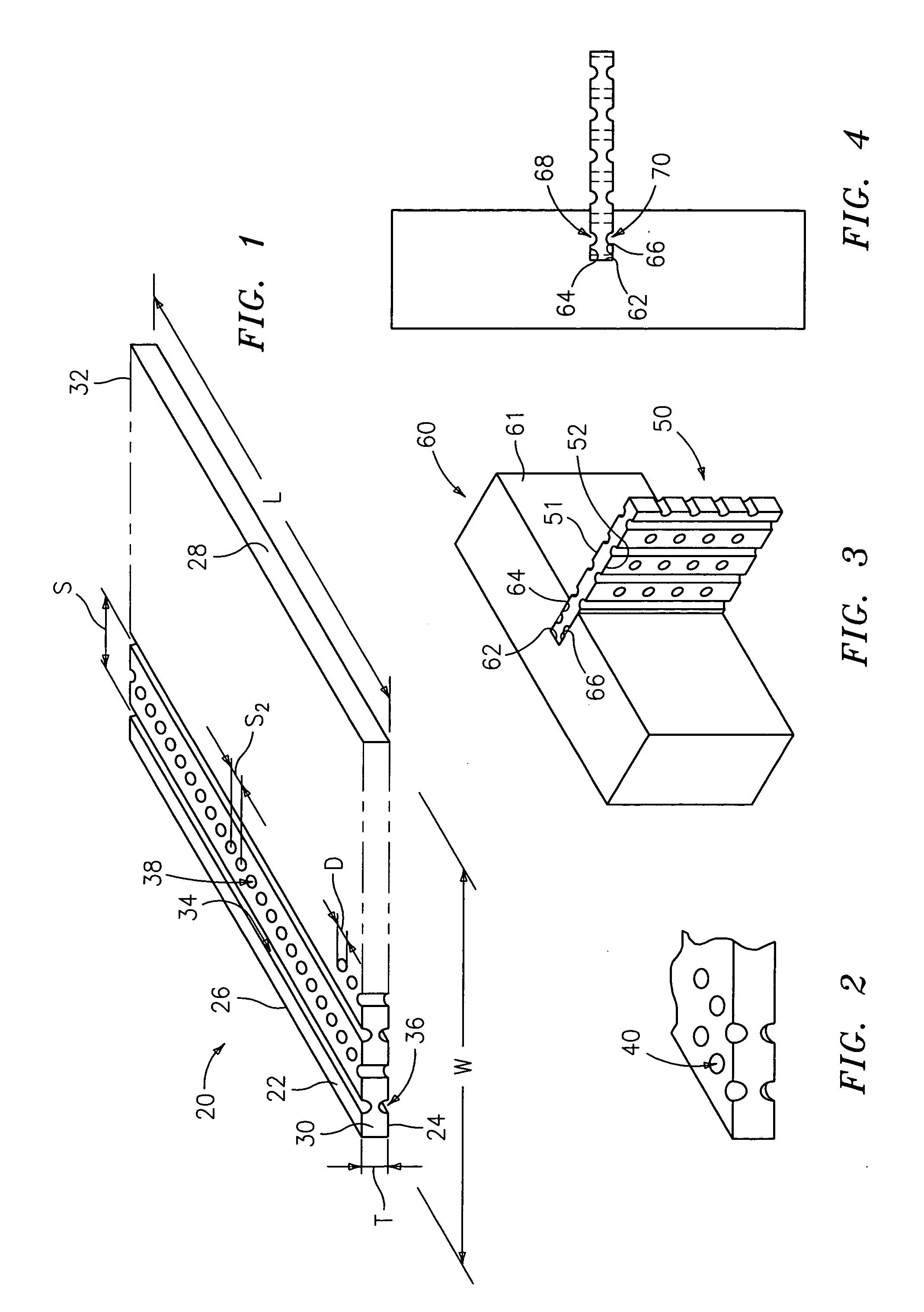
[0022]FIG. 1 shows a refractory metal-based sheet 20 for forming refractory metal cores for investment casting. Exemplary sheet materials include Mo, Nb, Ta, and W, alone or in combination and in elemental form, alloys, intermetallics, and the like. The exemplary sheet 20 is initially essentially flat having a thickness T between first and second surfaces 22 and 24. Exemplary thicknesses T are 0.2–5.0 mm. The sheet has a width W between perimeter edge surfaces 26 and 28 and a length L between perimeter end surfaces 30 and 32. Exemplary widths and lengths are much larger than T and may be from several centimeters upward.

[0023]According to one aspect of the invention, the sheet 20 may be pre-formed with surface features or other enhancements to serve one or more useful functions during the investment casting process. The exemplary sheet of FIG. 1 has enhancements including a first regular array of channel recesses 34 in the surface 22. The exemplary recesses 34 are linear at a constan...


PUM

PropertyMeasurementUnit
metallicaaaaaaaaaa
thicknessaaaaaaaaaa
lengthaaaaaaaaaa

Abstract

An investment casting pattern is formed by forming a metallic first core element including at least one recess. The first core element is engaged to at least a mating one of an element of the die and a second core element. The recess serves to retain the first core element relative to the mating one. The die is assembled and a sacrificial material is introduced to the die to at least partially embed the first core element. The recess may be pre-formed prior to cutting the first core element from a larger sheet of material.

Description

BACKGROUND OF THE INVENTION[0001]The invention relates to investment casting. More particularly, the invention relates to the forming of core-containing patterns for investment forming investment casting molds.[0002]Investment casting is a commonly used technique for forming metallic components having complex geometries, especially hollow components, and is used in the fabrication of superalloy gas turbine engine components.[0003]Gas turbine engines are widely used in aircraft propulsion, electric power generation, ship propulsion, and pumps. In gas turbine engine applications, efficiency is a prime objective. Improved gas turbine engine efficiency can be obtained by operating at higher temperatures, however current operating temperatures in the turbine section exceed the melting points of the superalloy materials used in turbine components. Consequently, it is a general practice to provide air cooling. Cooling is typically provided by flowing relatively cool air from the compressor...

Claims


Application Information

Patent Timeline
Patent Type & Authority Patents(United States)
IPC IPC(8): B22C9/04B22C1/00
CPCB22C7/02B22C9/04B22C9/10B22C21/14F01D5/147F05D2230/211F05D2230/21
Inventor SNYDER, JACOB A.BEALS, JAMES T.
Owner RTX CORP
Why Eureka
Try Eureka