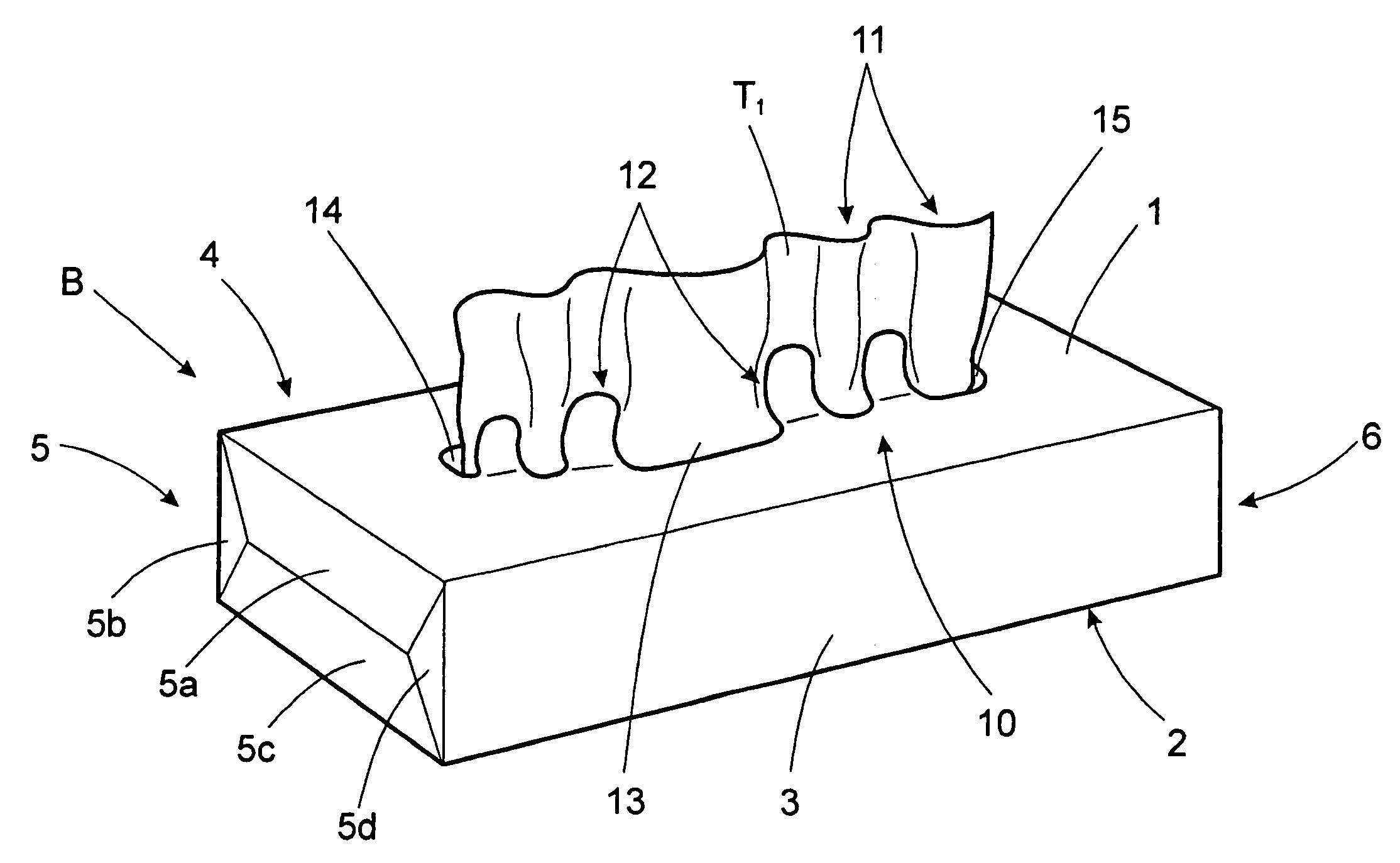
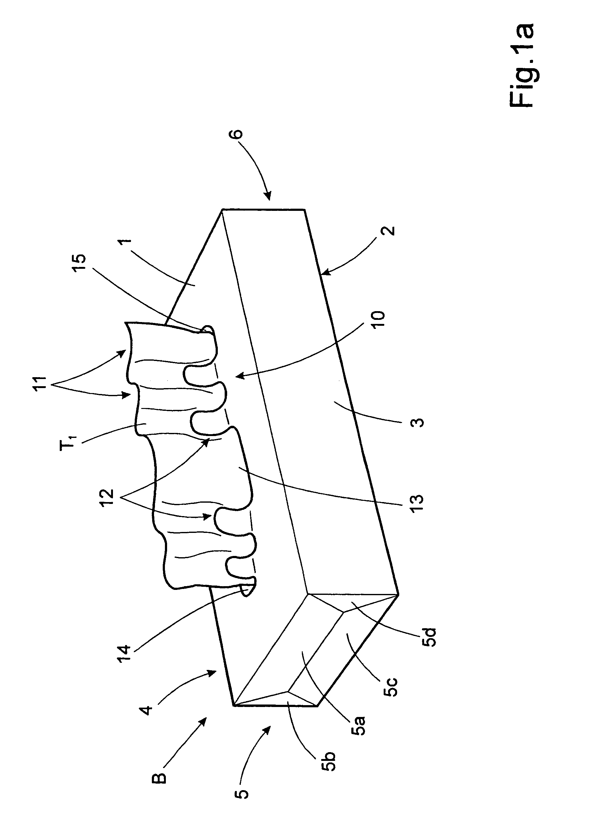
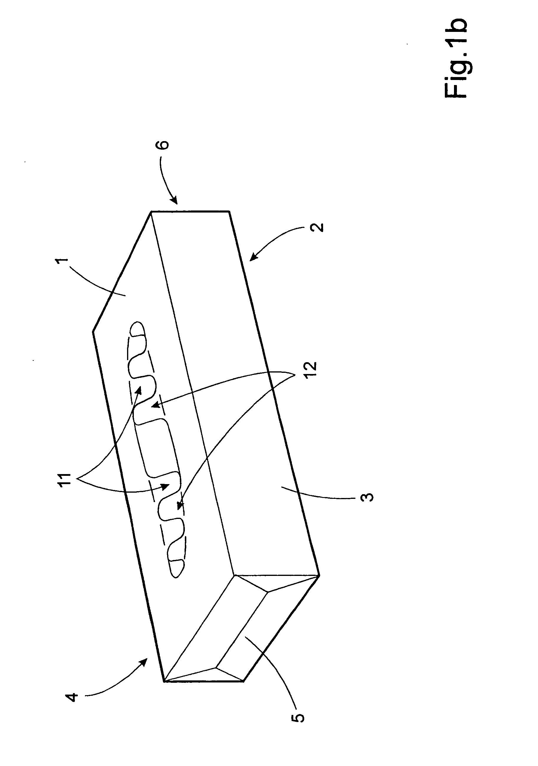
Container for a stack of interfolded tissue sheets
a tissue sheet and container technology, applied in the direction of containers, rigid containers, pile separation, etc., can solve the problems of difficult to get a good grip on the tissue or the edge of the tissue being presented, and the arrangement of opposing projections is not sufficient to keep the tissue in an upward presentation position, etc., to achieve the effect of simple and expedien
- Summary
- Abstract
- Description
- Claims
- Application Information
AI Technical Summary
Benefits of technology
Problems solved by technology
Method used
Image
Examples
second embodiment
[0070]FIG. 4b shows a plan view of the invention. Although the shape of the projections shown in FIG. 4b is the same as those shown in FIG. 4a, the box itself represents a further embodiment. This can be seen more clearly in FIG. 5, which shows a cross-section of the box in the transverse plane Y. According to this embodiment, the top wall 1 comprises two layers in the form of an upper top wall 1T, provided with a first set of projections 16′–16iv and a lower top wall 1B, provided with a second set of projections 17′–17iv. These walls would normally be attached to each other by means of an adhesive or glue, but for clarity the layers are shown slightly separated in FIG. 5. In its unopened condition, the box shown in FIG. 4b would have a cover section (see FIG. 7; “18”) covering the second set of projections 17′–17iv, the central cut-out 13 and the outer cut-outs 14, 15 in cut the lower top wall 1B. The box is opened by tearing off this cover section (not shown) is along a perforated...
third embodiment
[0072]FIG. 4c shows a plan view of a further, third embodiment of the invention, showing the overlapping, opposing projections in their inactive positions. The projections 16′, 16″, 16″′, 16iv; 17′, 17″, 17″′, 17iv and the central and outer cut-outs 13, 14, 15 have been described in connection with FIG. 2 above. The embodiment of FIG. 4c differs from that of FIG. 4a in that the upper wall 1 is made up of two layers. The projections are placed in a lower layer, while an upper layer is provided with a cover section (not shown). The cover section (see FIG. 8, “C”) is perforated around its outer periphery and is removed by the user when the box is opened, in order to expose the projections 16′, 16″, 16″′, 16iv; 17′, 17″, 17″′, 17iv and the embossed folding lines 10a, 10b. The resulting opening in the upper layer is therefore larger than that the area enclosed by the embossed folding lines and has an edge 19 placed at a distance from said embossed folding lines. A blank that can be erect...
fourth embodiment
[0073]FIG. 4d shows a plan view of the invention, showing the overlapping, opposing projections in their inactive positions. The projections 20′, 20″, 20″′, 20iv; 21′, 21″, 21″′, 21iv and the central and outer cut-outs 13, 14, 15 are part of an insert N attached to the underside of the top wall 1. Similar to the embodiment described in connection with FIG. 4c, the top wall 1 would be provided with a cover section (not shown). The cover section has a perforated line 19 around its outer periphery, as in the embodiment of FIG. 4c.The cover is removed by the user when the box is opened, in order to expose the projections 20′, 20″, 20″′, 20iv; 21′, 21″, 21″′, 21iv and the embossed folding lines 10d, 10e. As described above, all projections, cut-outs would be cut or punched as a single continuous line. The insert would also be provided with folding lines embossed directly onto the insert. The insert itself is preferably made from a suitable plastic material.
[0074]FIG. 5 shows a cross-sect...
PUM
| Property | Measurement | Unit |
|---|---|---|
| Time | aaaaa | aaaaa |
| Angle | aaaaa | aaaaa |
| Angle | aaaaa | aaaaa |
Abstract
Description
Claims
Application Information
 - R&D
- Intellectual Property
- Life Sciences
- Materials
- Tech Scout
- Unparalleled Data Quality
- Higher Quality Content
- 60% Fewer Hallucinations
Browse by: Latest US Patents, China's latest patents, Technical Efficacy Thesaurus, Application Domain, Technology Topic, Popular Technical Reports.
© 2025 PatSnap. All rights reserved.Legal|Privacy policy|Modern Slavery Act Transparency Statement|Sitemap|About US| Contact US: help@patsnap.com


