Vorticity cancellation at trailing edge for induced drag elimination

a technology of induced drag and vorticity, applied in the direction of propellers, air-flow influencers, transportation and packaging, etc., can solve the problems of reducing the effective angle of attack, not contradicting, and unable to terminate the vorticity, so as to achieve the effect of increasing suction power and potential saving thrust power

Inactive Publication Date: 2006-11-14
LOTH JOHN L
View PDF17 Cites 30 Cited by
  • Summary
  • Abstract
  • Description
  • Claims
  • Application Information

AI Technical Summary

Benefits of technology

[0037]In accordance with the present invention, the methods required to cancel the upper and lower surface boundary layer vorticity upon shedding from the trailing edge of a finite wing or rotor blade has been described in detail. To accomplish this feat with an elliptically loaded wing would require far more suction power than the potential gain in thrust power savings. Only by configuring the finite wing or rotor blade to have constant bound circulation, so that the upper and lower surface boundary layer vorticity cancels each other upon shedding from the trailing edge, will the power required reduce to less than 10% of the thrust power saved. This makes it a desirable technology for future aircraft, helicopters, propellers and fans.

Problems solved by technology

These methods do not contradict Hemholt's theorems which state that vorticity cannot be terminated within an ideal fluid.
Then deflecting both ailerons upwards will reduce their effective angle of attack.

Method used


Image

  • Vorticity cancellation at trailing edge for induced drag elimination
  • Vorticity cancellation at trailing edge for induced drag elimination
  • Vorticity cancellation at trailing edge for induced drag elimination

Examples


Embodiment Construction

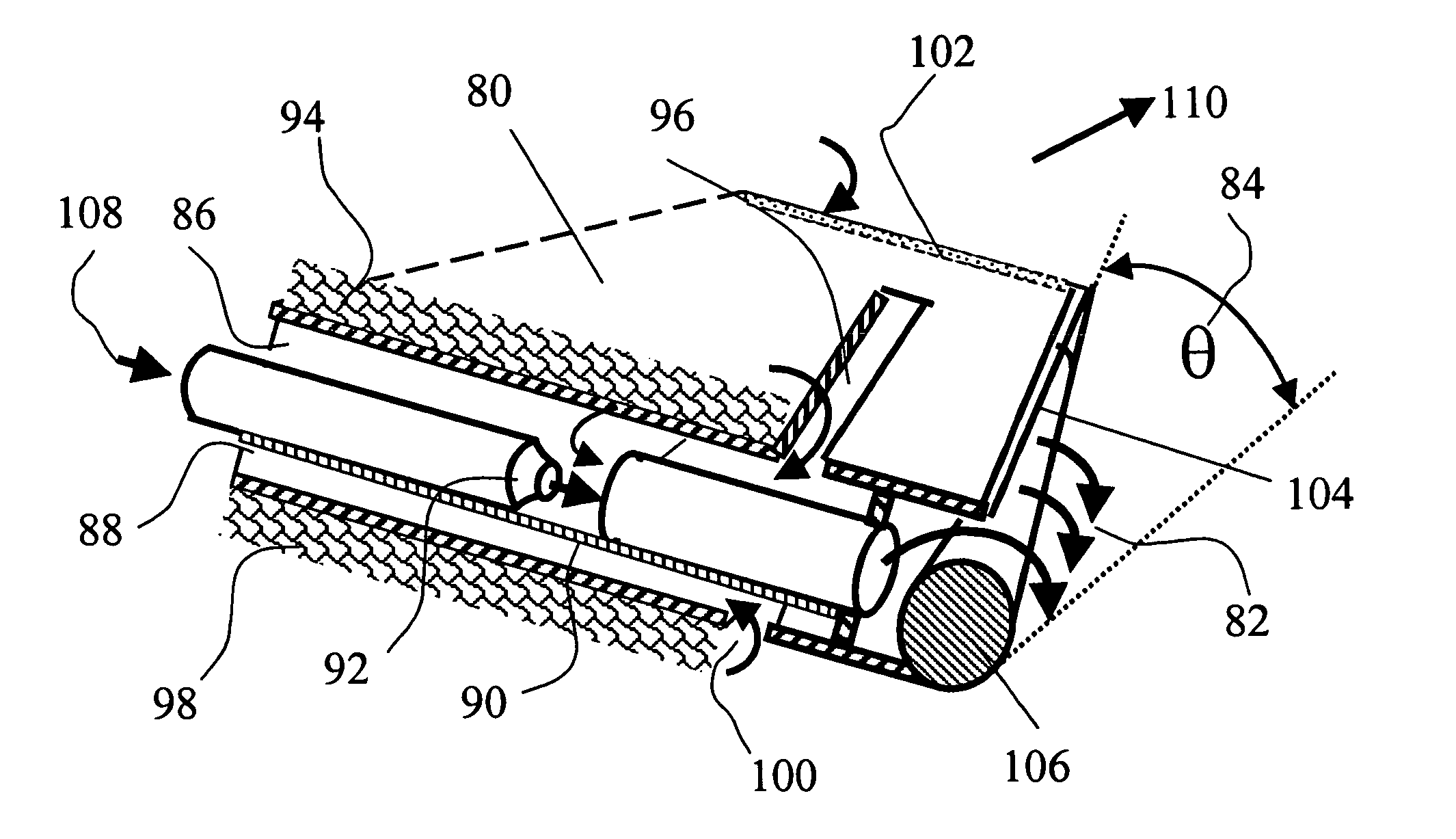
[0046]FIG. 1 shows the trailing edge segment of a 2-D wing 10 mounted in a wind tunnel, between two opposing walls. To achieve true 2-D loading and performance on this wing, the following methods have been applied. Numerous small holes 14 have been drilled through the tunnel wall 12 with the proper level of vacuum applied to remove only the tunnel boundary layer so as to maintain a uniform lift generating relative wind 16 over the wing. Boundary layer control by suction is applied to assure that the bound circulation contained within the boundary layer, remains aligned in the span-wise direction. The upper boundary layer 22 is removed through upper slot 18 while the lower boundary layer 24 through lower slot 20 at the intersection between the airfoil and the tunnel wall. This assures uniform 2-D loading of the wing along its entire span. To prevent short-circuiting of the higher-pressure air below the wing to the lower pressure air above the wing, suction slots 18 and 20 are separat...


PUM


Abstract

Wing tip vortices are evident from airliner vapor trails, and helicopter blade slap. Elliptically loaded high aspect ratio tapered wings have minimum induced drag but cannot eliminate it. Different methods are disclosed herein, for upper and lower surface boundary layers to cancel their opposing vorticity upon shedding from the trailing edge, thereby eliminating wake vorticty, induced drag and associated noise. This requires wing-rotor-propeller or fan blades with a platform designed for uniform bound circulation and with boundary layer control near the tip. In addition this requires special techniques to counter span-wise pressure gradients, such as tip circulation control blowing or an upwind small propeller or wind turbine on each tip. These techniques can eliminate wake vorticity with its induced drag, noise, flying on the backside of the power curve and the option for asymmetric loading by pneumatic means to eliminate need for cyclic pitch control or conventional ailerons.

Description

BACKGROUND OF THE INVENTION[0001]1. Field of Invention[0002]This invention relates to methods for a lifting body to eliminate induced drag and noise, by canceling the vorticity, generated in its upper and lower surface boundary layers, upon leaving the trailing edge, thus keeping it out of the wake. This technology applies to any lifting body such as a wing, helicopter rotor, propeller, fan blade, etc.[0003]2. Prior Art[0004]A powerful relation in theoretical aerodynamics was developed independently by German mathematician W. Kutta (1867–1944) and Russian mathematician N. Jouwkowski (1847–1921) and is called the Kutta-Joukowski theorem for a two-dimensional (2-D) lift producing body in an ideal fluid, which has no viscosity. Such a body produces lift per unit span equal to the sum of the up wash momentum in front of and the equal but opposite downwash momentum behind the lifting body. The lift per unit span produced is given in vector form by {right arrow over (L)}=ρ({right arrow ov...

Claims


Application Information

Patent Timeline
Patent Type & Authority Patents(United States)
IPC IPC(8): B64C21/06
CPCB64C11/001B64C21/08B64C23/065Y02T50/164Y02T50/166Y02T50/66B64C2230/28Y02T50/10Y02T50/60
Inventor LOTH, JOHN L.
Owner LOTH JOHN L
Why Eureka
Try Eureka