Scalloped surface turbine stage

a surface turbine and turbine technology, applied in the field of turbines, can solve the problems of unsatisfactory reduction of overall turbine efficiency, turbine pressure loss, horseshoe vortex, etc., and achieve the effect of reducing horseshoe vortex a

Active Publication Date: 2006-11-14
GENERAL ELECTRIC CO
View PDF21 Cites 137 Cited by
  • Summary
  • Abstract
  • Description
  • Claims
  • Application Information

AI Technical Summary

Problems solved by technology

Undesirable pressure losses in the combustion gas flowpaths therefore correspond with undesirable reduction in overall turbine efficiency.
One common source of turbine pressure losses is the formation of horseshoe vortices generated as the combustion gases are split in their travel around the airfoil leading edges.
The interaction of the pressure and suction side vortices occurs near the midspan region of the airfoils and creates total pressure loss and a corresponding reduction in turbine efficiency.
These vortices also create turbulence and increase undesirable heating of the endwalls.
Since the horseshoe vortices are formed at the junctions of turbine rotor blades and their integral root platforms, as well at the junctions of nozzle stator vanes and their outer and inner bands, corresponding losses in turbine efficiency are created, as well as additional heating of the corresponding endwall components.

Method used


Image

  • Scalloped surface turbine stage
  • Scalloped surface turbine stage
  • Scalloped surface turbine stage

Examples


Embodiment Construction

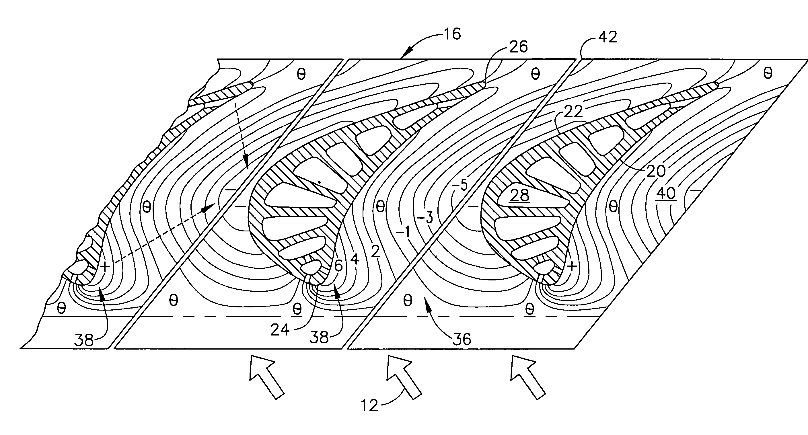
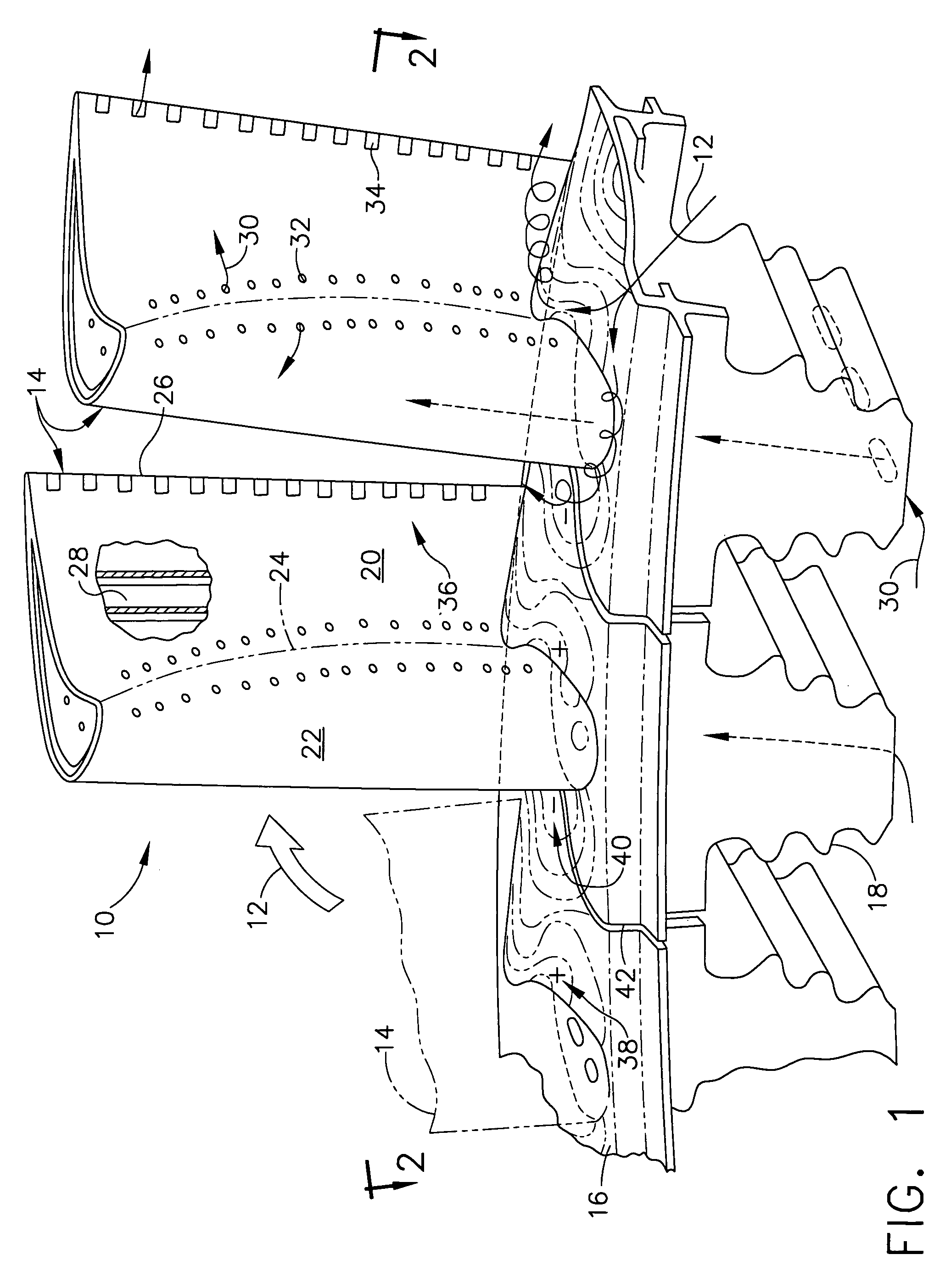
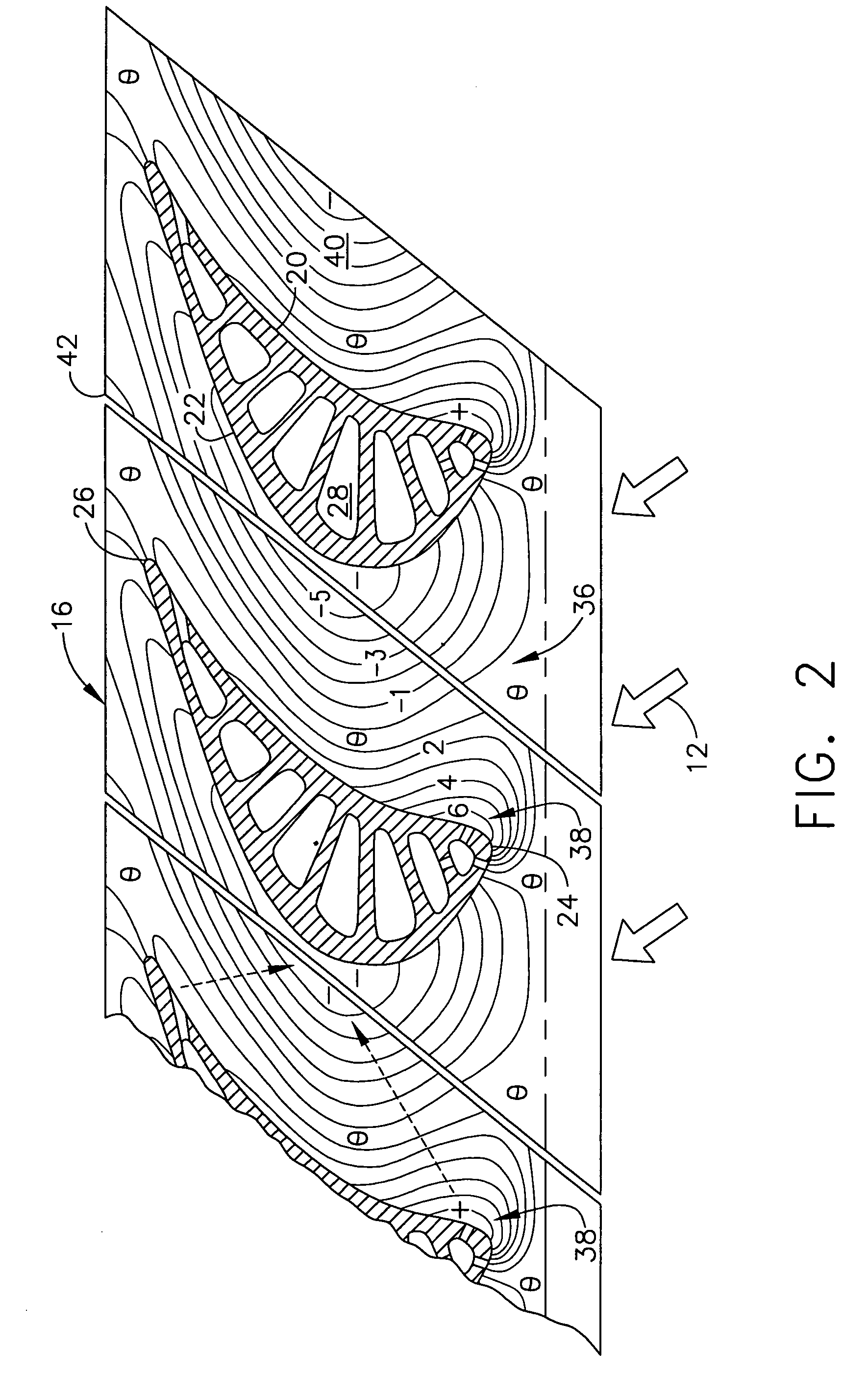
[0023]Illustrated in FIG. 1 are two exemplary first stage turbine rotor blades 10 which circumferentially adjoin each other in a full row thereof in a corresponding turbine stage of a gas turbine engine. As indicated above, combustion gases 12 are formed in a conventional combustor (not shown) and discharged in the axial downstream direction through the row of turbine blades 10 which extract energy therefrom for powering a supporting rotor disk (not shown) on which the blades are mounted.

[0024]The turbine stage includes a complete row of the blades, with each blade having a corresponding airfoil 14 integrally joined at a root end to a corresponding radially inner endwall or platform 16. Each platform is in turn integrally joined to a corresponding axial-entry dovetail 18 conventionally configured for supporting the corresponding turbine blade in the perimeter of the rotor disk.

[0025]Each airfoil includes a generally concave pressure side 20 and a circumferentially or laterally oppos...


PUM


Abstract

A turbine stage includes a row of airfoils joined to corresponding platforms to define flow passages therebetween. Each airfoil includes opposite pressure and suction sides and extends in chord between opposite leading and trailing edges. Each platform has a scalloped flow surface including a bulge adjoining the pressure side adjacent the leading edge, and a bowl adjoining the suction side aft of the leading edge.

Description

BACKGROUND OF THE INVENTION[0001]The present invention relates generally to gas turbine engines, and, more specifically, to turbines therein.[0002]In a gas turbine engine air is pressurized in a compressor and mixed with fuel in a combustor for generating hot combustion gases. Turbine stages extract energy from the combustion gases to power the compressor, while also powering an upstream fan in a turbofan aircraft engine application, or powering an external drive shaft for marine and industrial applications.[0003]A high pressure turbine (HPT) immediately follows the combustor and includes a stationary turbine nozzle which discharges combustion gases into a row of rotating first stage turbine rotor blades extending radially outwardly from a supporting rotor disk. The HPT may include one or more stages of rotor blades and corresponding turbine nozzles.[0004]Following the HPT is a low pressure turbine (LPT) which typically includes multiple stages of rotor blades and corresponding turb...

Claims


Application Information

Patent Timeline
Patent Type & Authority Patents(United States)
IPC IPC(8): F01D5/22
CPCF01D5/143F01D5/145Y02T50/673F05D2250/711F05D2250/70F05D2250/712F05D2240/80Y02T50/60
Inventor TAM, ANNALEE, CHING-PANGKIRTLEY, KEVIN RICHARDBUNKER, RONALD SCOTTLAMSON, SCOTT HENRYCARSON, SCOTT MICHAEL
Owner GENERAL ELECTRIC CO
Why Eureka
Try Eureka