
Overhead work and mold storage platform for plastic injection molding machine

a technology of injection molding machine and storage platform, which is applied in the direction of auxillary shaping apparatus, manufacturing tools, ceramic shaping apparatus, etc., can solve the problems of inability to use machines as ladders, interference with work flow, and inability to meet the needs of workers, etc., to achieve efficient operation, reduce labor intensity, and optimize available work space

Inactive Publication Date: 2006-11-14
INDAL TECH & SERVICES
View PDF3 Cites 8 Cited by
  • Summary
  • Abstract
  • Description
  • Claims
  • Application Information

AI Technical Summary

Benefits of technology

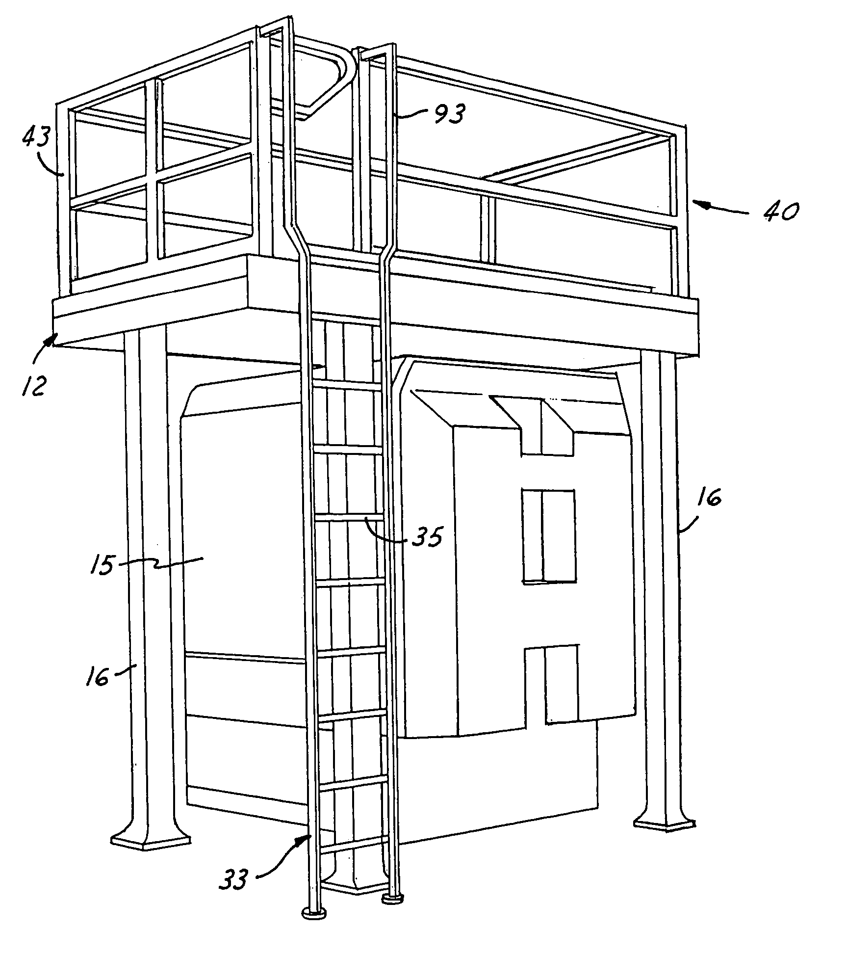
[0005]The present invention offers a solution to the aforementioned problems. The elevated or overhead platform of the mold or tool access and storage structure provides a maintenance worker with direct access to the top of the machine. In addition, the elevated platform provides a storage area for molds or tools above the machine, with the molds / tools being moveable into and out of the machine by an overhead crane. In the past, molds for the injection molding machine have occupied floor space surrounding the machine. In addition, the tools or molds are stored within the envelope of the machine. Thus, without the molds on the floor, the plant has greater flexibility for the layouts of machines in the work areas and provides for greater flow of the work in process.
[0006]In addition, with the molds stored above the machine on the elevated or overhead work platform, a much quicker or faster procedure for changing molds is provided which benefits the economics of this technology. It is appreciated that the overhead crane has a shorter distance to move to the top of the machine, manipulate the tools or molds and to replace the tools / molds in the machine.
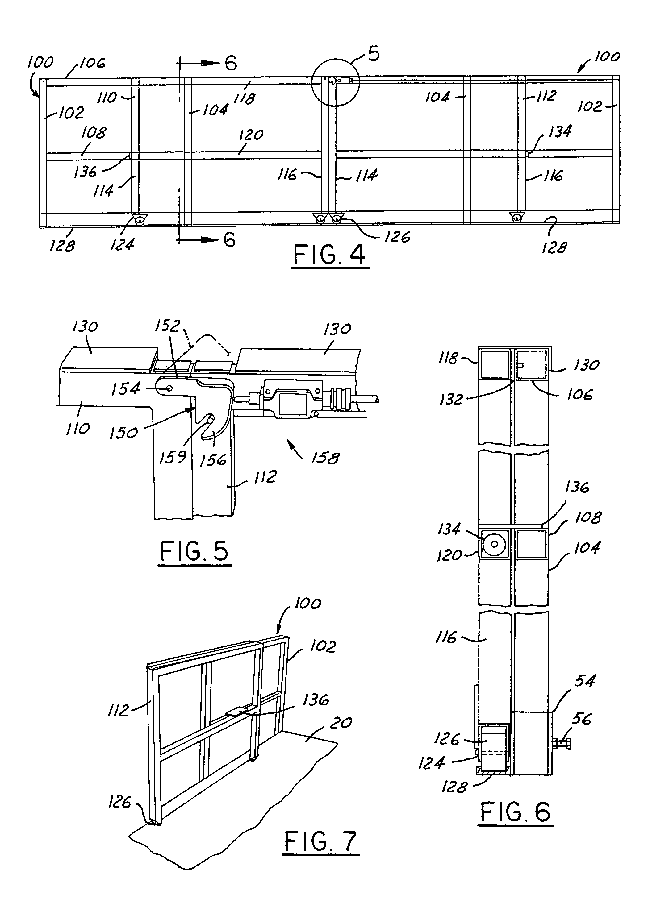
[0015]A further feature of the present invention is to provide a mold access and storage structure of the aforementioned type wherein the slideable rail panels are provided with rollers engageable with tracks mounted along the walkway which permit the gates to roll freely.
[0018]The final feature of the present invention is to provide a mold access and storage structure of the aforementioned type which is engineered to optimize available work space, provide for safety and product changeover, is economical to manufacture, efficient in operation and may be disassembled and then reassembled to permit major repair and / or reconstruction of the injection molding machine.

Problems solved by technology

For access to the tops of the machines, it is extremely difficult to reach without using the machines as ladders.
Such use of the machines as ladders is unacceptable to state and federal agencies involved with plant safety, personnel and environmental issues.
The storage of molds at the base of the machine or in the surrounding areas interferes with the work flow.

Method used


Image

  • Overhead work and mold storage platform for plastic injection molding machine
  • Overhead work and mold storage platform for plastic injection molding machine
  • Overhead work and mold storage platform for plastic injection molding machine

Examples


Embodiment Construction

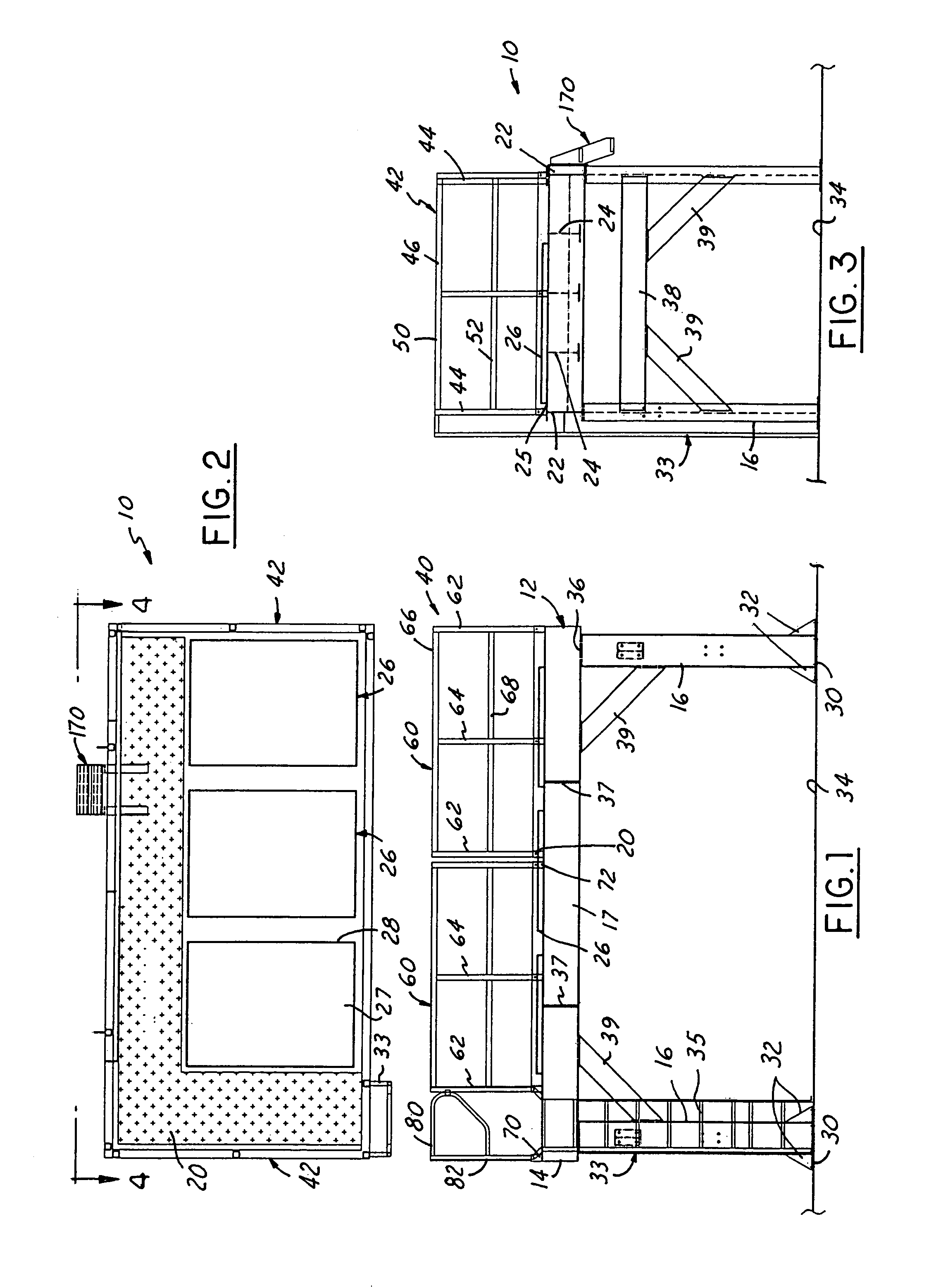
[0036]The mold access and storage structure is designated by the numeral 10. It includes an elevated work platform 12 having a generally rectangular horizontally extending steel frame 14 supported generally at the corners thereof by upstanding vertical columns or legs 16. The legs 16 are attached to the frame 14 and straddle a machine 15 (FIG. 15), as an example, an injection molding machine, for holding the elevated work platform 12 above the machine. Each column 16 may be an I-beam or other structural steel member capable of carrying the load.

[0037]The steel frame 14 is made from a pair of longitudinally extending, transversely spaced apart I-beam deck girders 17 having an upper flange 18 and a lower flange 20 as shown in FIG. 16. A pair of transversely extending I-beams 22 (FIG. 3) are provided with end plates and are located between and fastened to adjacent ends of the I-beam deck girders 17 to provide the generally rectangular frame 14. The frame 14 further includes a plurality...


PUM

PropertyMeasurementUnit
lengthaaaaaaaaaa
lengthaaaaaaaaaa
lengthaaaaaaaaaa

Abstract

The mold access and storage structure comprises an elevated work platform of generally rectangular configuration which is supported at the comers thereof by columns which straddle a machine. The top of the platform includes a walkway and a plurality of spaced apart parallel oil and water containment reservoirs or pans for receiving and storing molds when not in use by the machine and for collecting any oil or lubricant draining from the mold. A vertical ladder permits a person to access the work platform for maintenance purposes. A railing enclosure is mounted around the top of the platform and extends around the outer periphery of the walkway and reservoirs. The railing enclosure includes a pair of slideable gates which, when open, prevents the machine from operating and permits a ladder to be pivoted and moved from the walkway, into the space between the open slideable gates, thereby permitting a maintenance worker to access the top of the machine.

Description

BACKGROUND OF THE INVENTION[0001]1. Field of the Invention[0002]The present invention relates to a mold access and storage structure for a machine, as an example, an injection molding machine, where an overhead work platform supported by a plurality of legs straddle the machine for holding the platform above the machine. Molds or tools are stored in areas provided in the platform and workmen can access the machine from the platform for repair and maintenance purposes.[0003]2. Description of the Prior Art[0004]The plastic industry uses large machines, as an example, 500 to 1750 ton injection molding presses. For access to the tops of the machines, it is extremely difficult to reach without using the machines as ladders. Such use of the machines as ladders is unacceptable to state and federal agencies involved with plant safety, personnel and environmental issues. The storage of molds at the base of the machine or in the surrounding areas interferes with the work flow.SUMMARY OF THE P...

Claims


Application Information

Patent Timeline
Patent Type & Authority Patents(United States)
IPC IPC(8): B29C33/70B29C37/00
CPCB29C37/00B29C33/70
Inventor PIERIK, STEVEN H.WELSH, JOHN E.
Owner INDAL TECH & SERVICES
Learn More