

Coordinated brake control system
- Summary
- Abstract
- Description
- Claims
- Application Information
AI Technical Summary
Benefits of technology
Problems solved by technology
Method used
Image

Examples
first embodiment
[0023]Referring to FIGS. 1 through 9E, there is discussed a coordinated brake control system for a hybrid brake system in accordance with the present invention.
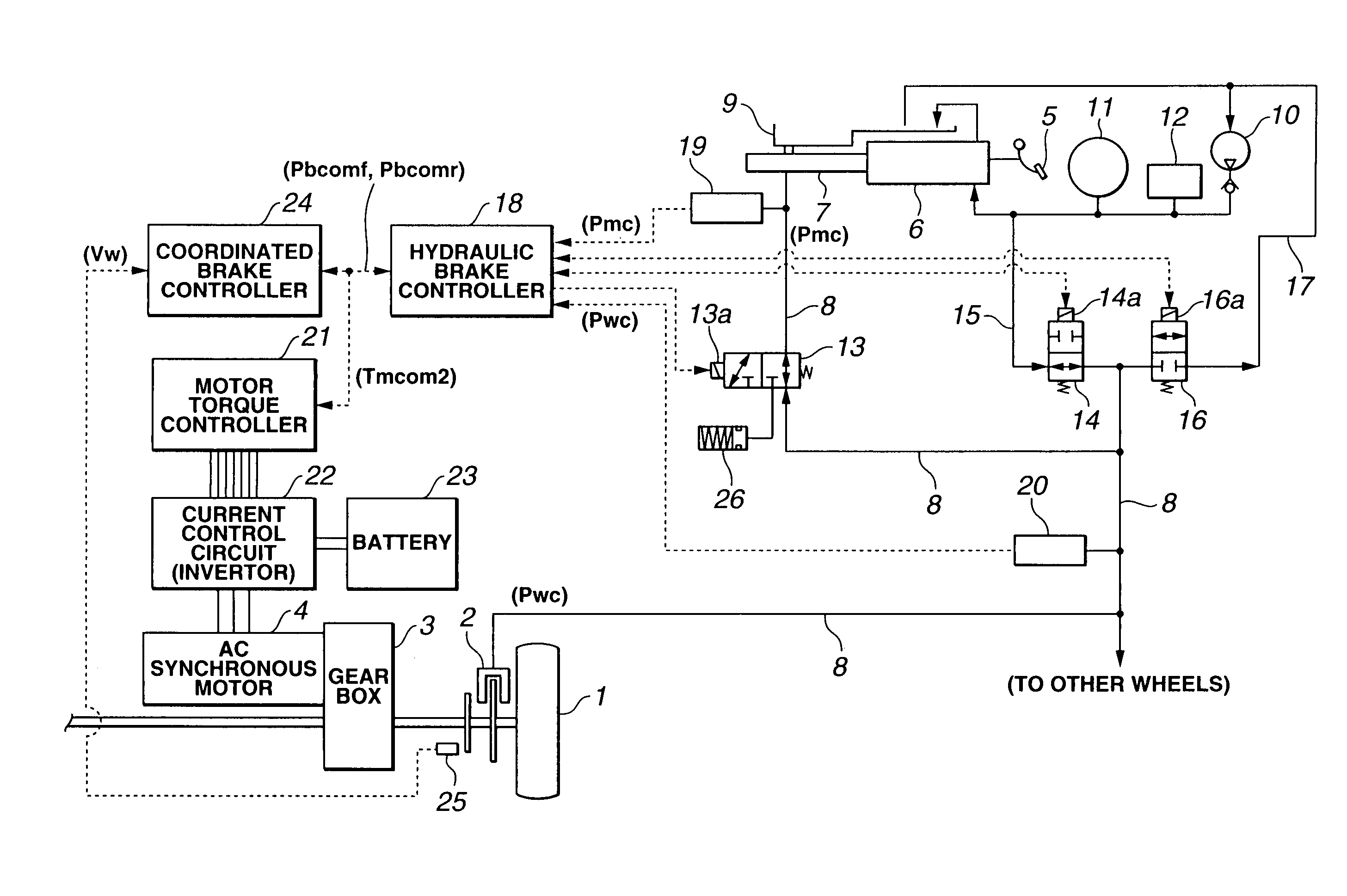
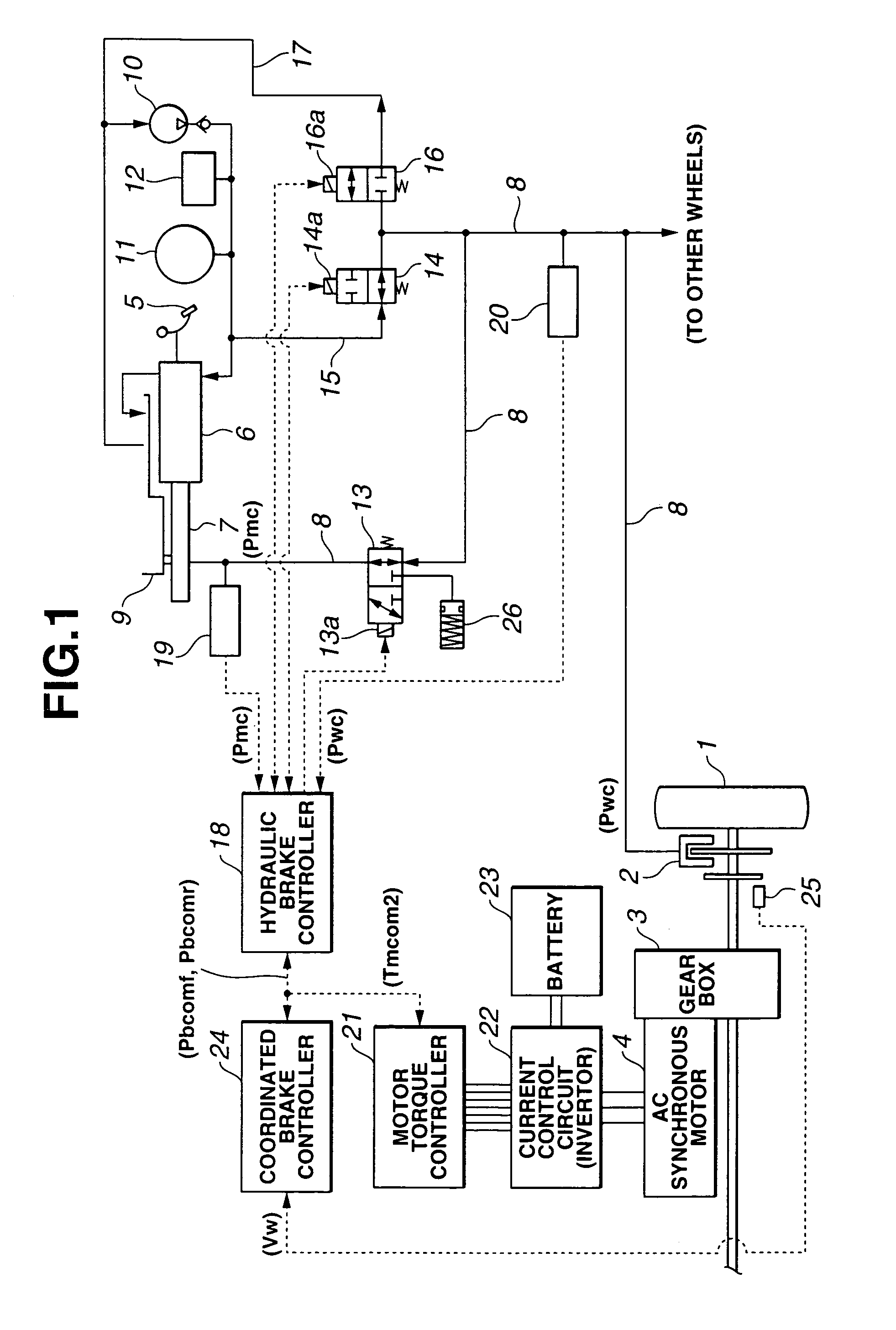
[0024]FIG. 1 shows the hybrid brake system comprising the coordinated brake control system according to the first embodiment of the present invention. The hybrid brake system comprises a hydraulic brake unit of generating a braking torque (braking force) by supplying a hydraulic pressure to a wheel cylinder 2 provided for each driving wheel 1 (in FIG. 1, only one wheel is shown), and a regenerative brake unit of converting a wheel rotating energy into an electric power by means of an alternating-current (AC) synchronous motor 4 which is connected to driving wheel 1 through a gear box 3.
[0025]The coordinated brake control system for the hybrid brake system is arranged to effectively recover a regenerative energy by decreasing a braking hydraulic pressure to wheel cylinder 2 during when the braking torque (force) is mainly prod...
second embodiment
[0085]When final regenerative braking-torque Tmlmt is obtained by multiplying allowable maximum regenerative braking-torque Tmmax and regenerative braking-torque limit coefficient Kv (Tmlmt=Tmmax×Kv) and when the obtained final generative braking-torque Tmlmt is employed for the calculation of final regenerative braking-torque command value Tmcom2, as shown in FIGS. 10A through 10E, particularly in FIG. 10C, the degree of decrease of the regenerative torque at the moment t2 from when the changeover (transition) from the regenerative braking to the friction braking is started. Therefore, the increase of the wheel cylinder hydraulic pressure (friction braking-torque) command value Pbcomf during a short period just after the moment t2 is suppressed. Consequently, the coordinated brake control system of the second embodiment prevents the actual wheel cylinder pressure from largely separating from the wheel cylinder pressure command value regardless of the large delay of the actual wheel...
third embodiment
[0091]Accordingly, the third embodiment according to the present invention is capable of corresponding the rate of change of the wheel cylinder hydraulic pressure command value Pbcomf with a response delay of the friction braking torque throughout the changeover period from the regenerative braking torque to the friction braking torque (corresponding to a period from the moment t2 to the moment t3 during when vehicle speed VSP is decreased from regenerative braking-torque limit start speed Vlmth to regenerative braking-torque limit finish speed Vlmtl). This enables the total braking-torque to be brought closer to a target braking torque even during the changeover period, and removes a strange feeling caused by a shortage of the deceleration or the change of the deceleration of the vehicle throughout the changeover period from the moment t2 to the moment t3.
PUM
 Abstract
Description
Claims
Application Information