Trip manifold

a manifold and manifold technology, applied in the field of manifolds, can solve the problems of difficult maintenance, cumbersome design of such systems, and difficulty in etc., and achieve the effect of safe removal, service and maintenance or replacemen

Active Publication Date: 2006-11-21
EMERSON PROCESS MANAGEMENT POWER & WATER SOLUTIONS
View PDF10 Cites 7 Cited by
  • Summary
  • Abstract
  • Description
  • Claims
  • Application Information

AI Technical Summary

Benefits of technology

[0007]In the transmit position, fluid communication is provided by the manifold and header shaft between the input source and the pressure transmitter. In the drain position, the transmitter is isolated and pressure is released from the valve to the drain vent. Thus, in the drain position, the transmitter may be safely removed and examined for service, maintenance or possible replacing. By providing multiple valves and transmitters on a header shaft, multiple redundancy pressure transmitters may be provided for a single input source. Because each valve and transmitter can be rotated to the drain position without interfering with the function of the other valves and transmitters, a single valve and transmitter can be moved to the drain position to release pressure within the valve and the transmitter can be safely removed, serviced and maintained or replaced without interfering with the operation of the other valves and transmitters. In this manner, a transmitter may be replaced without interfering with the operation of the remaining components of the manifold and therefore the turbine, engine or other apparatus being monitored may continue to run or stay on-line while a transmitter is replaced or serviced. In a preferred embodiment, three valves and three transmitters are disposed on the header shaft for each transmitter input passage and drain passage.

Problems solved by technology

Of course, other components may form part of an emergency tripping system such as anticipator trip valves which may be tripped or activated by excessive speed of the turbine.
One problem associated with emergency tripping systems for industrial turbines, engines and other similar apparatuses is the cumbersome design of such systems.
Specifically, transmitters are prone to failure and require frequent maintenance.
With the common use of multiple redundant transmitters or multiple redundant distributed control system (DCS) inputs for each trip function, the piping, wiring and mounting for the various trip functions becomes cumbersome to install and difficult to maintain.
Still further, due to the cumbersome design of these systems, there is no easy way to gain access to the transmitters or valves for service and maintenance.

Method used


Image

  • Trip manifold
  • Trip manifold
  • Trip manifold

Examples


Embodiment Construction

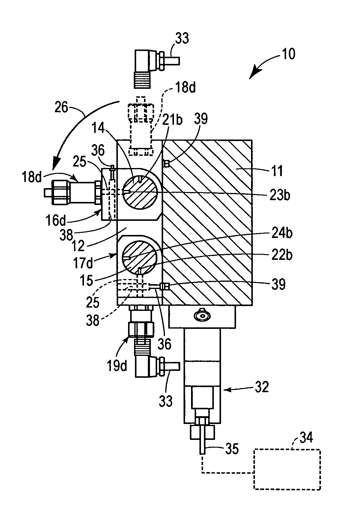
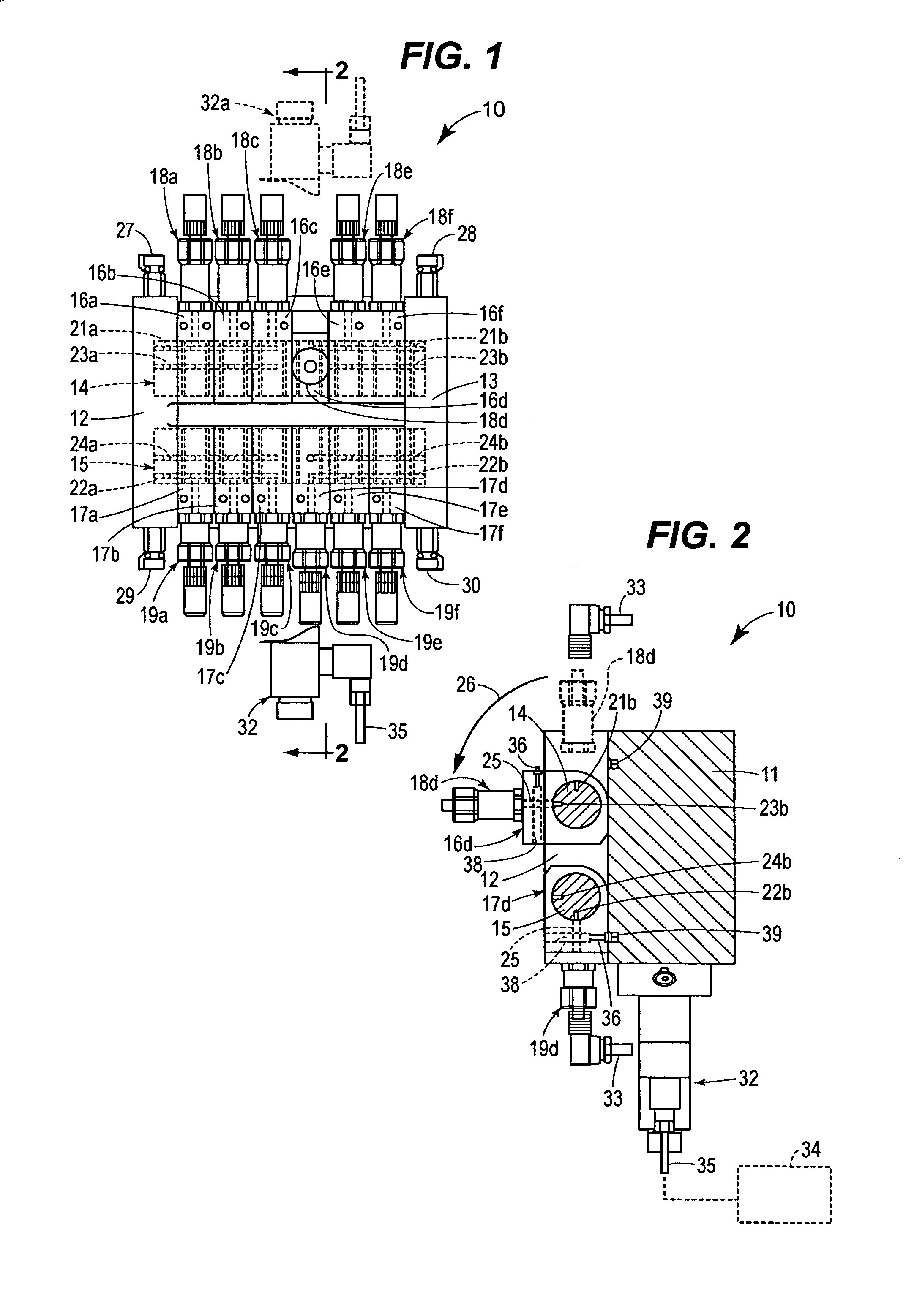
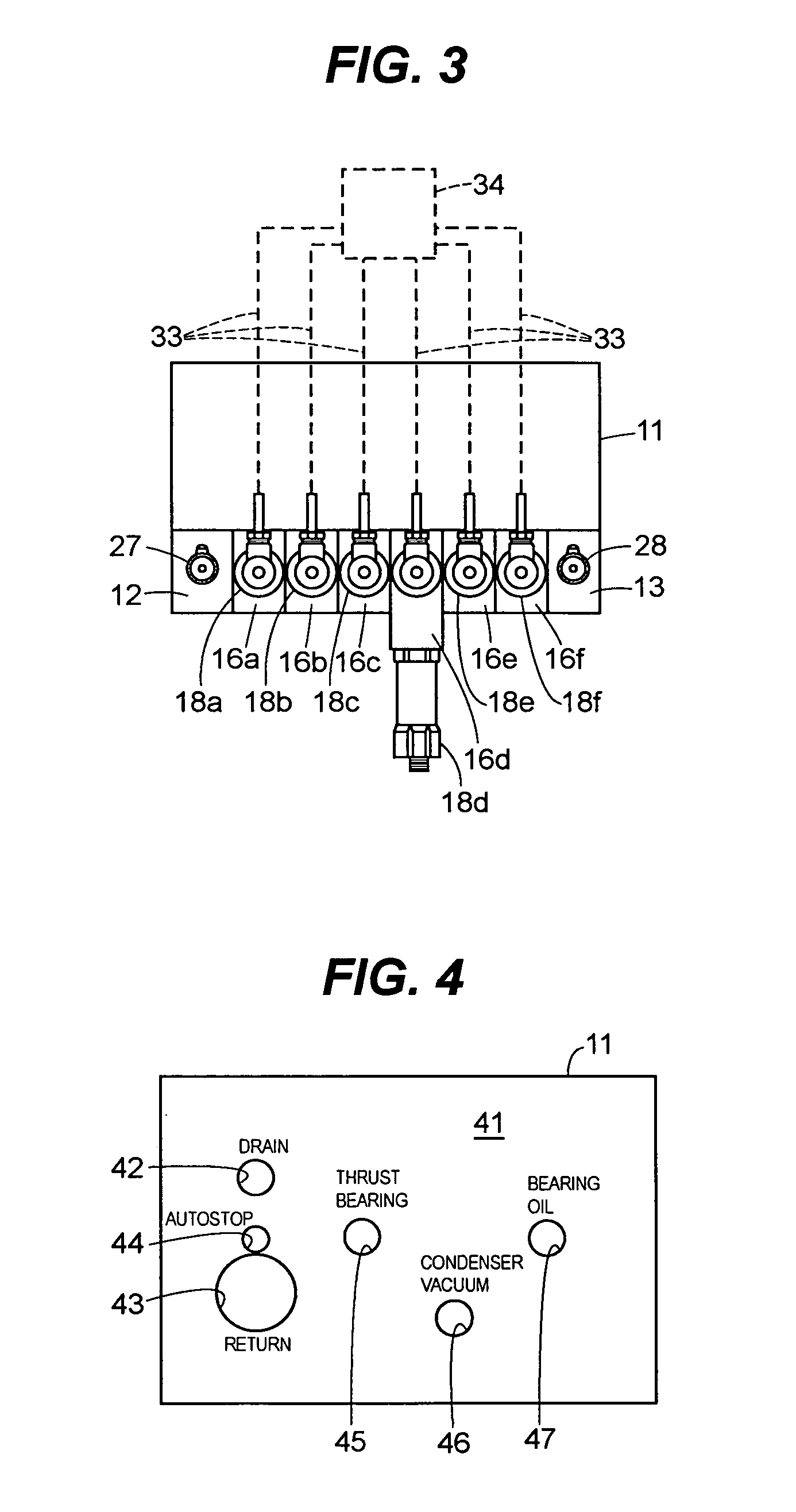
[0023]FIGS. 1–4 illustrate a trip manifold assembly 10 which is particularly useful for Westinghouse steam turbines but it will be apparent to those skilled in the art that the disclosed manifold assemblies 10 are also adaptable to other turbines, such as those manufactured by General Electric, and other industrial devices that require monitoring such as generators, engines and the like.

[0024]Referring to FIGS. 1 and 2, the manifold assembly 10 includes a manifold body 11 which is connected to two spaced apart support blocks 12, 13. The support blocks 12, 13 may be an integral part of the manifold body 11 or attached separately thereto. The support blocks 12, 13 are connected to and support the header shafts 14, 15. The header shafts 14, 15 are fixedly connected to the support blocks 12, 13 and do not rotate. In the embodiments shown in FIGS. 1–4, two header shafts 14, 15 are provided. It will be also understood that the advantages of the design could be accomplished with a single h...


PUM


Abstract

A trip manifold assembly is disclosed which includes a manifold body connected to a header shaft. The header shaft passes through a plurality of rotary valves. Each rotary valve is connected to a pressure transmitter. The header shaft comprises two passages including a transmitter input passage and a drain passage. The rotary valves each comprise a through passage. A manifold body provides fluid communication between an input source and the transmitter input passage of the header shaft. The manifold also provides communication between the drain passage of the header shaft and a drain vent. The rotary valves are each independently rotatable between two positions including a transmit position where the through passage of each valve provides communication between the transmitter input passage of the header shaft and their respective pressure transmitters. Each rotary valve is also independent rotatable to a drain position where the through passage of each valve is in communication with the drain passage of the header shaft. Multiple header shafts may be provided in a single manifold assembly and each header shaft can handle more than one input that needs to be monitored.

Description

TECHNICAL FIELD[0001]An emergency trip manifold for a turbine or other piece of industrial equipment is shown and described. More specifically, the trip manifold provides a compact design with multiple pressure readings of multiple sources. Pressure transmitters may be removed or serviced while the system is still operating. The disclosed manifold replaces the cumbersome emergency tripping systems currently used with industrial turbines and other devices where it is imperative to keep certain pressure readings, such as bearing oil pressures, thrust bearing oil pressures, condenser vacuum pressures and / or exhaust pressures within a certain predetermined range.BACKGROUND OF THE RELATED ART[0002]Emergency tripping systems have long been utilized to shut off industrial turbines in the event certain operating conditions occur. Such tripping systems are commonly designed around certain pressure readings. Those pressure readings, and the maintenance of such pressures within a prescribed ra...

Claims


Application Information

Patent Timeline
Patent Type & Authority Patents(United States)
IPC IPC(8): F16K37/00
CPCF01D17/08F01D21/16F05D2270/301Y10T137/87885Y10T137/8175F01D21/14F01D21/18
Inventor SWEENEY, THOMASNATILI, JR, RICHARD PETERWOLFE, MATTHEW E.
Owner EMERSON PROCESS MANAGEMENT POWER & WATER SOLUTIONS
Why Eureka
Try Eureka