Heddle shaft with center connector

a technology of center connector and shaft rod, which is applied in the direction of weaving, other shedding mechanisms, textiles and paper, etc., can solve the problems of long shaft rod, large mass of shaft rod, and inability to optimize maximum weaving speed, so as to facilitate the introduction of adhesives and facilitate the expansion of the shaft rod. the effect of rigidity

Inactive Publication Date: 2006-11-21
GROZ BECKERT KG
View PDF29 Cites 4 Cited by
  • Summary
  • Abstract
  • Description
  • Claims
  • Application Information

AI Technical Summary

Benefits of technology

[0012]The invention makes it possible to provide wide heddle shafts with long shaft rods, and these heddle shafts are suitable for high weaving speeds. No separate chamber for clamping pieces or the like for securing center connectors is needed. Very lightweight shaft rods, which are intrinsically not intended for constructing heddle shafts with center connectors, can therefore be used. Hence the corresponding hollow chamber profile bodies can be cut to the proper length from an endless profile from which normally only shorter shaft rods are made.
[0014]Securing the retaining piece in the hollow chamber is preferably done by means of an adhesive connection; it is preferable that the retaining piece be seated in the hollow chamber with only little play, while the adhesive is not yet hardened. This makes it possible to position the retaining piece in the hollow chamber, introduce adhesive, and process or manipulate the applicable shaft rod further without taking particular consideration of the adhesive connection, which may not yet be capable of withstanding a load.
[0015]Moreover, it is considered advantageous if the retaining piece spans the window, provided for attaching the center connector, in the longitudinal direction of the shaft. Thus the weak point in the shaft rod created by the retaining window is closed with regard to its bending strength. Given a suitable overlap, the rigidity of the shaft rod in the region of the window can even be increased beyond the otherwise existing amount.
[0016]It is considered advantageous to provide the shaft rod and / or the retaining piece with a means that facilitates the introduction of adhesive. Such a means may comprise one or more conduits, which are embodied in the retaining piece and / or in the shaft rod and by way of which the adhesive can be introduced into the desired adhesive seam from outside. Such conduits may be formed for instance by one or more transverse bores of the retaining piece, which communicate with one or more adhesive introduction openings provided in the side walls of the shaft rod. The retaining piece preferably has at least one adhesive pocket, which can store a certain quantity of adhesive so that from this reserve, the adhesive seam to be formed can be supplied with adhesive.
[0017]The retaining piece may be a plastic body or a metal body or a combined plastic and metal body. For instance, threaded bushes can be embedded in a plastic body, as a result of which the retaining piece is on the one hand lightweight and rigid and on the other is suitable for sturdy attachment of the center connector by means of screws.

Problems solved by technology

For wide weaving widths, the result is very long shaft rods, which tend to sagging, as a function of the weaving speed (number of revolutions).
This arrangement is not optimized for maximum weaving speeds.
Moreover, the embodiment of a longitudinally continuous chamber for the clamping piece requires increased consumption of material and thus results in a considerable mass for the shaft rod.

Method used


Image

  • Heddle shaft with center connector
  • Heddle shaft with center connector
  • Heddle shaft with center connector

Examples


Embodiment Construction

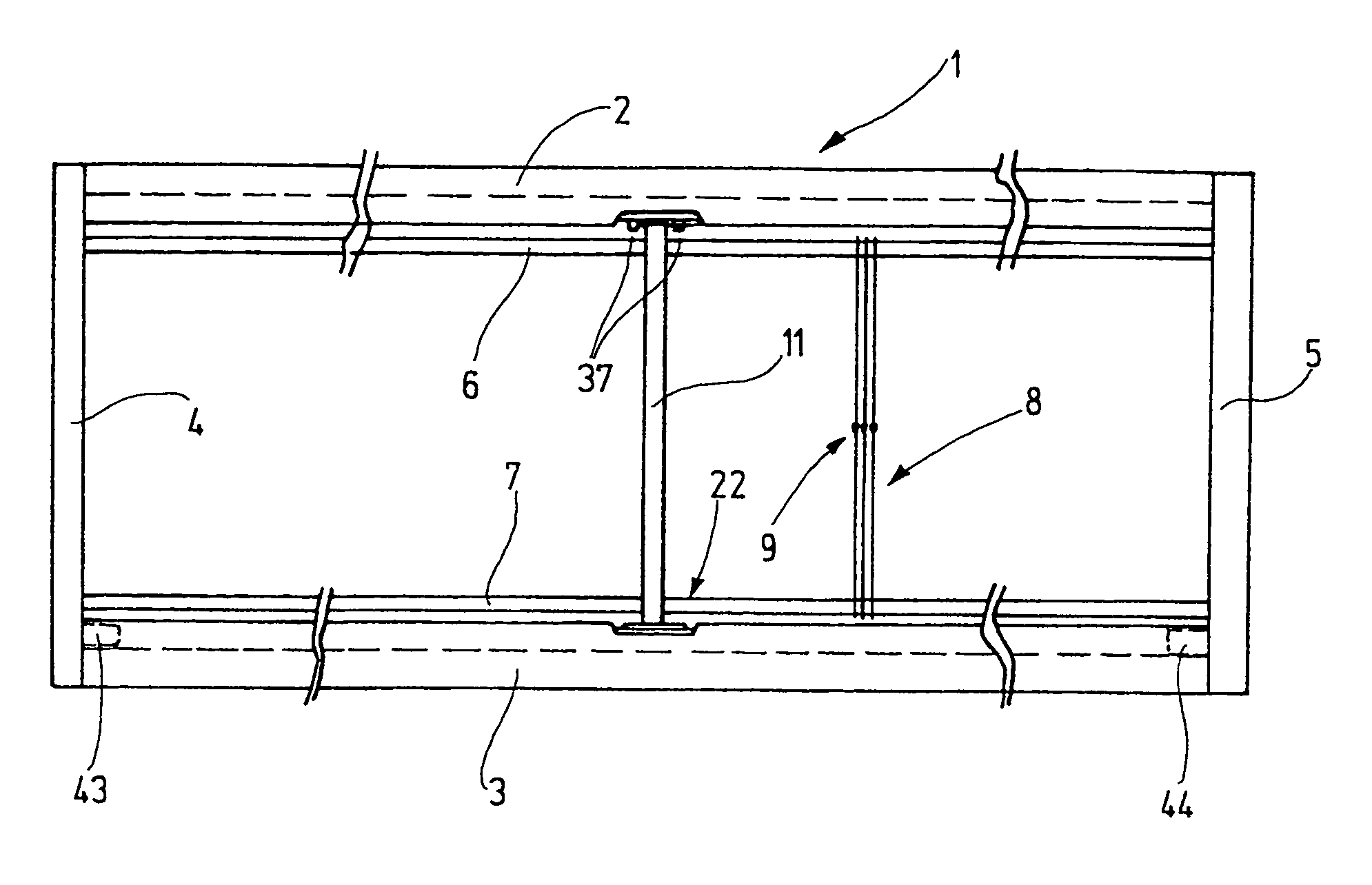
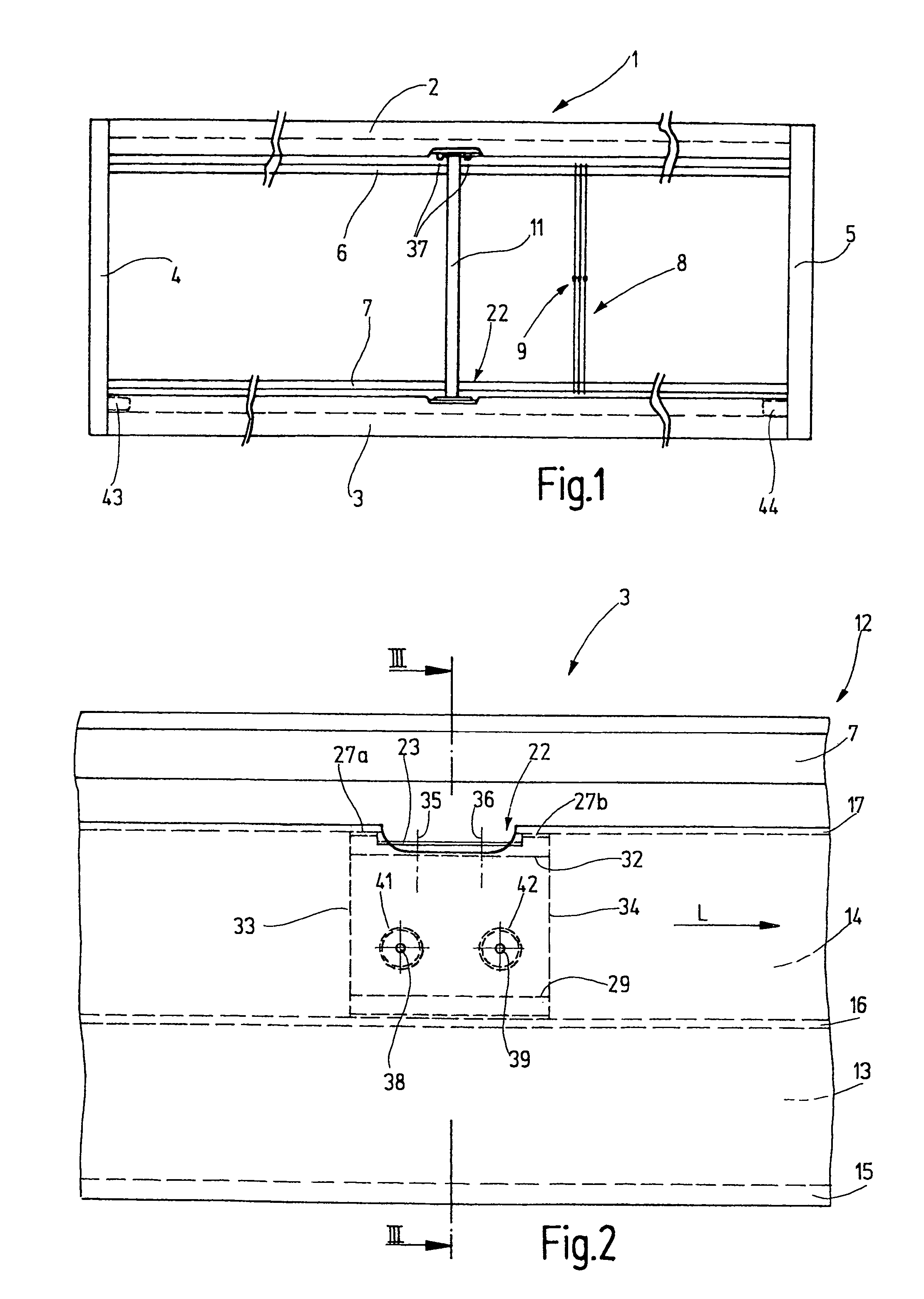
[0024]In FIG. 1, a heddle shaft 1 is shown which has an upper shaft rod 2, a lower shaft rod 3, and lateral bracing posts 4, 5. The shaft rods 2, 3, kept spaced apart and parallel, together with the lateral bracing posts 4, 5 form a rectangular frame. One heddle support rail 6, 7 is retained on each shaft rod 2, 3, and between these rails a large number of heddles 8 are retained. Each of the heddles 8 has at least one yarn eyelet 9, through which a warp thread is guided. In the up-and-down motion of the heddle shaft 1, this warp thread is moved up or down to form sheds.

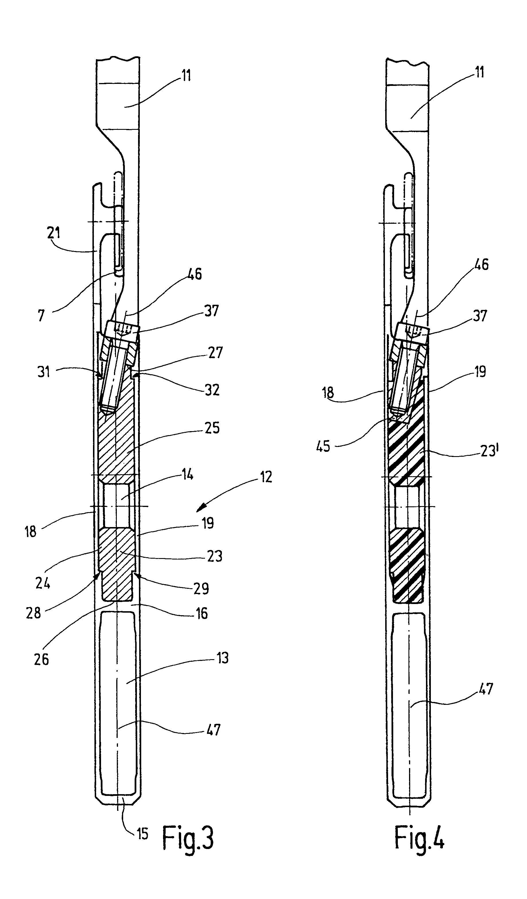
[0025]The shaft rods 2, 3 are joined together between their lateral bracing posts by one or more center connectors 11 extending approximately parallel to the lateral bracing posts 4, 5. The center connectors 11 may be provided in the middle between the lateral bracing posts 4, 5 and / or additionally at other points, and they extend parallel to the lateral bracing posts 4, 5. They serve to suppress or damp uncontrolled ...


PUM


Abstract

A heddle shaft (1) has shaft rods (2, 3), which are embodied as profile bodies (12) having at least one hollow chamber (14). The shaft rods (2, 3) are joined together by lateral bracing posts (4, 5) and at least one center connector (11). For securing the latter, retaining pieces (23) are disposed in the hollow chambers and are accessible through windows (22). The retaining pieces (23) are preferably glued into the hollow chamber (14) and have one or more threaded bores for securing the center connector (11) by means of screws (37).

Description

CROSS REFERENCE TO RELATED APPLICATION[0001]This application claims the priority of German Patent Application No. 103 49 383.2, filed on Oct. 21, 2003, the subject matter of which, in its entirety, is incorporated herein by reference.FIELD OF THE INVENTION[0002]The invention relates to a heddle shaft which is suitable for power looms, especially high-speed power looms.BACKGROUND OF THE INVENTION[0003]So-called heddle shafts are used for shedding in power looms. The heddle shafts are formed by a frame that is essentially rectangular in a front elevation view and whose upper and lower long, longitudinal edges are each formed by one shaft rod. Laterally, the shaft rods are joined by lateral bracing posts. The shaft rods are often formed by hollow chamber profiles. Heddle support rails that support the heddles are secured to the shaft rods. Each heddle has at least one yarn eyelet, through which a warp thread is guided. For shedding, the heddle shafts are moved up and down in rapid succ...

Claims


Application Information

Patent Timeline
Patent Type & Authority Patents(United States)
IPC IPC(8): D03C9/06D03C13/00
CPCD03C9/0658
Inventor OLBING, ANDREGESING, KARL-HEINZ
Owner GROZ BECKERT KG
Why Eureka
Try Eureka