Enhanced cold chamber die casting molding machine

a technology of injection apparatus and cold chamber die casting, which is applied in the direction of molten metal supply equipment, chemistry apparatus and processes, manufacturing tools, etc., can solve the problems of high operating cost of the above-described conventional molding method machine, inoperable furnace for a whole day, and long time to raise or lower the furnace temperature, so as to reduce the heating energy of the melting device and accelerate the maintenance work of the injection apparatus. , the effect of improving the heating efficiency

Inactive Publication Date: 2006-11-21
SODICK CO LTD
View PDF30 Cites 11 Cited by
  • Summary
  • Abstract
  • Description
  • Claims
  • Application Information

AI Technical Summary

Benefits of technology

[0020]The inside diameter of a portion of the cylinder bore distal to the billet inserting device matches the outside diameter of a solid, enlarged, heated billet so as to prevent backward flow of the molten metal, and the inside diameter of a portion of the cylinder bore adjacent to the billet inserting device is slightly larger than the outside diameter of each billet.
[0036]In this measuring method, since the opening and shutting operation of the material supplying hole by means of the opening and shutting device and the extruding operation of molten metal by means of the plunger are performed simultaneously, solidification of molten metal in the material supplying hole is prevented. Furthermore, adhesion of molten metal to the material supplying hole or the valve rod is prevented, ensuring accurate measurement control.

Problems solved by technology

The above-described conventional molding method machine have a high operating cost, since the size of the furnace is much larger than that of the molded articles, and since a great volume of molten metal needs to be kept at a specified high temperature.
Additionally, it takes a long time to raise or lower the furnace temperature, and maintenance work may render a furnace inoperable for a whole day.
Moreover, and especially in the case of easily oxidized magnesium alloy molding materials, it is necessary to occasionally remove the magnesium oxide sludge.
The surface area of the molten metal in the furnace is too large to prevent the generation of the sludge, although much non-burning flux or inert gas is poured into the furnace, and this sludge causes wear of the injection sleeve and the plunger.
This type of conventional injection apparatus generally injects semi-solidified molding material into the mold, solving the furnace-related problems and decreasing the potential for oxidation of a magnesium alloy.
Therefore, the troublesome problems associated with Japanese Patent No. 2639552 are solved, increasing of the variety of the ingots and the related preliminary heating condition settings, making it unnecessary to pre-prepare many kinds of ingots for every molded article.
The above-described injection apparatus of both the hot chamber method machine and the cold chamber method machine include some furnace-related problems.
Also, the injection apparatus described in Japanese Patent No. 2639552 and Japanese Patent Laid-Open No. 2001-191168, which do not contain a furnace, have such a limitation that they are not suitable for molding particularly thin walled and / or precise geometry articles, since they are do not inject fully molten metal.
When these types of injection apparatus attempt injection with fully molten molding material, a longer waiting time is required to change the material into a fully molten matter.
Japanese Patent Laid-Open No. Rei. 05-212531, which uses the self-consumption plunger, does not disclose the length of the molding material or its supply method.
Moreover, Japanese patent laid-open No. Rei. 05-212531 does not describe the solution to the problem of impeded plunger movement, which often makes injection process impossible.
This problem occurs since the molten metal, which has low viscosity and high pressure, flows backward through the gap between the injection sleeve and the self-consumption plunger, and then is solidified, accompanying increased frictional resistance.
In the case where a self-consumption type plunger is installed horizontally in the injection sleeve, the above-described problem becomes more remarkable, since the gap between the plunger and the injection sleeve is larger at its raised side, since the outside diameter of the self-consumption plunger is manufactured somewhat thinner than the inside diameter of the injection sleeve anticipating thermal expansion.
The above-described problem also becomes more pronounced in the case where the solidified matter of the molten metal is destroyed and re-formed at many times of injection molding operation and, as a result, grows up widely and hardly.
In particular, in the case of molding for a particularly thin-walled shape and / or a particularly complicated geometry shape, the occurrence of the problem becomes more remarkable, since an injection is carried out under high speed and / or high pressure conditions.
Japanese patent laid-open No. Rei. 05-254858 does not solve the above-described problem either, since it discloses seizure prevention technology for forming glass.
However in the case of light metal molding, light metal melts and solidifies rapidly due to small specific heat, small latent heat, and high coefficient of thermal conductivity inherent to light metal.
Accordingly, the conventional injection apparatus are still incomplete with regard to the stable injection of molten light metal.

Method used


Image

  • Enhanced cold chamber die casting molding machine
  • Enhanced cold chamber die casting molding machine
  • Enhanced cold chamber die casting molding machine

Examples


first embodiment

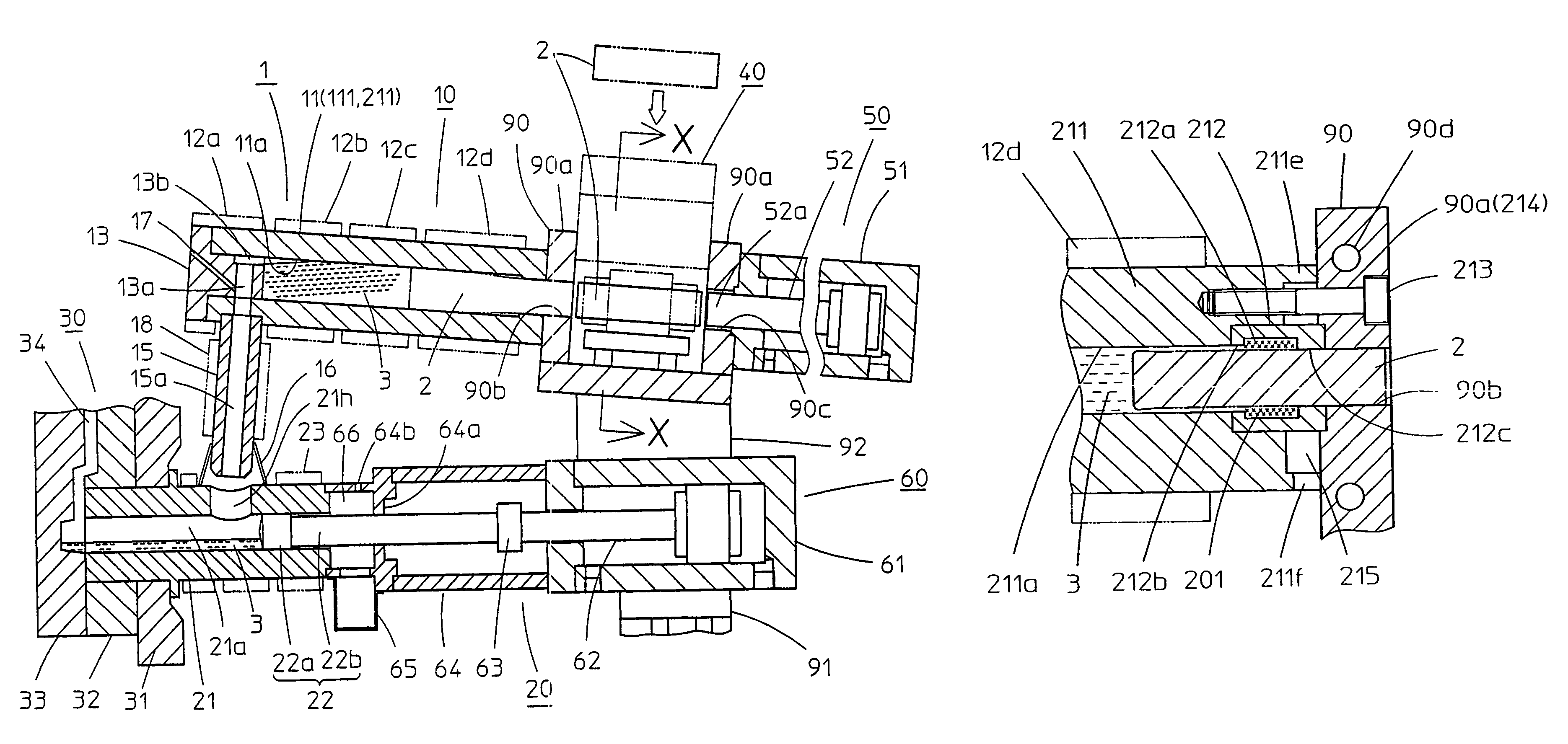
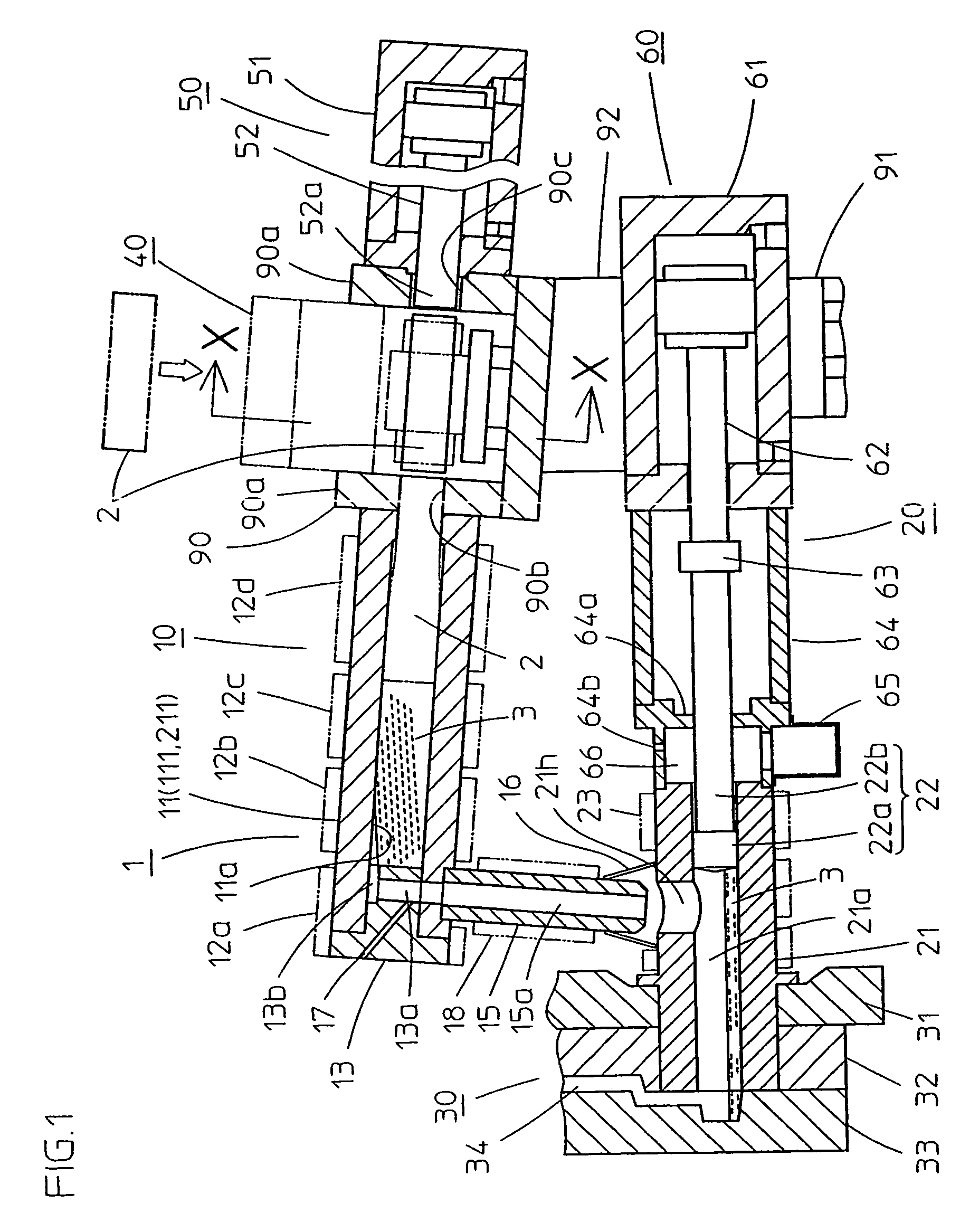
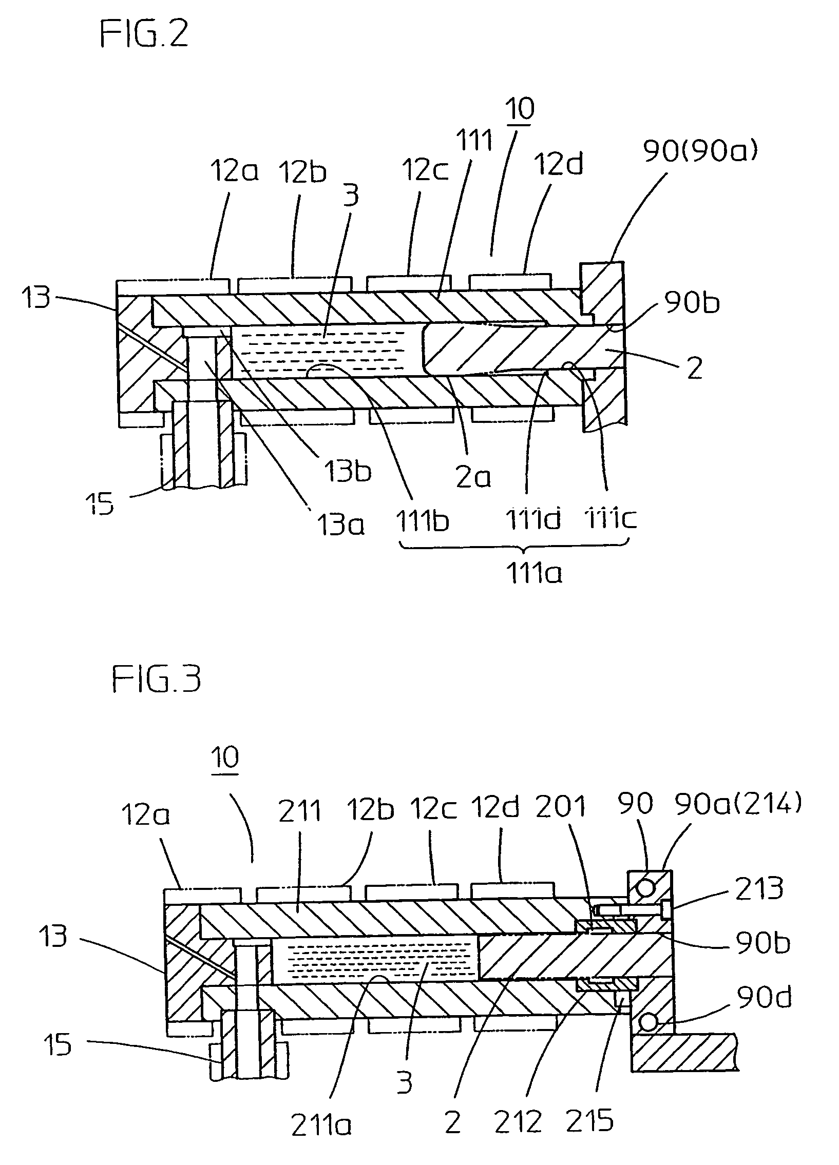
[0078]In the first embodiment, at the time of measuring, the front end of the softened billet 2 is enlarged diametrically slightly due to the slight rising pressure of the molten metal 3. A side surface 2a of the enlarged front end seals molten metal 3 by being appropriately kept into contact with the wall surface of the larger diameter cylinder bore 111b appropriately. This sealing is performed when the enlarged side surface 2a appropriately keeps contact with the wall surface of the cylinder bore 111b, and this sealing is realized by the appropriate gap size between them.

[0079]It is convenient that the rising pressure of the molten metal 3 is small at the time of measuring, preventing much of the diametrical expansion of the side surface 2a. Eccentricity of the billet 2 with the cylinder bore 111b is suppressed and the gap between the base end side cylinder bore 111c and billet 2 becomes small and equally minimized.

[0080]The side surface 2a keeps appropriate contact with the cylin...

second embodiment

[0083]On the other hand, in the second embodiment, molten metal 3 is not sealed by the above-described enlarged diameter seal member, but rather is sealed by a circular solidified material seal which is the solidified matter of molten metal 3 in the annular groove 212a of the cooling sleeve 212. The seal of the circular solidified material seal is described below.

[0084]In the case of magnesium alloys, the billet 2 in the cooling sleeve 212a is controlled to be at about 400° C., which is near its softening temperature, by being powerfully cooled by cooling sleeve 212. In this condition, when the injection apparatus 1 first commences its preparatory injection molding operation, the billet 2 advances at a slow speed, as is described below. The molten metal 3, which has already melted at the front end of the melting cylinder 211, flows backward along the billet 2, filling up the annular groove 212a, and changing into solidified matter. This solidified matter, as the circular solidified ...


PUM

PropertyMeasurementUnit
diameteraaaaaaaaaa
lengthaaaaaaaaaa
temperaturesaaaaaaaaaa

Abstract

An injection apparatus in a cold chamber die casting molding machine, where a melting device of the injection apparatus includes a billet supplying device for replenishing a light metal material in the form of a billet, a melting cylinder for melting the billet from its front end and forming a molten metal for several shots, an inserting device for inserting a billet into the melting cylinder, and a plunger injection device. The amount of a molten metal for one shot is measured via an opening and shutting device of a molten metal feeding member and is fed from the melting device to the plunger injection device. In particular, the sealing of the molten metal in the melting cylinder is achieved by the contact of the side surface of a portion of the billet having an enlarged diameter with the hole of the cylinder, or by the contact of a circular solidified material formed in a circular groove in a cooling sleeve with the billet. The injection apparatus can be used for feeding and melting a light metal materiel such as a magnesium alloy material with better efficiency and measuring the amount of a molten metal with higher accuracy.

Description

FIELD OF THE INVENTION[0001]The present invention generally relates to an injection apparatus for a cold chamber die casting molding machine and, more specifically, relates to an injection apparatus which replenishes a light metal material into its melting device in the form of a short cylindrical rod billet, and supplies the molten metal into a plunger injection device. Moreover, the present invention relates to a measuring method for the cold chamber die casting molding machine.DESCRIPTION OF THE RELATED ART[0002]Injection molding machine for light metal alloys, such as magnesium, aluminum or zinc, are generally known as die casting molding machines, and are categorized as either a “hot chamber method” machine or a “cold chamber method” machine. The hot chamber machine, which positions an injection device on a furnace, measures one shot of the molten metal in an injection sleeve of the injection device by sucking the molten metal from the furnace, and injects it into a mold cavity...

Claims


Application Information

Patent Timeline
Patent Type & Authority Patents(United States)
IPC IPC(8): B22D17/10B22D39/00B22D17/00B22D17/08B22D17/26B22D17/28B22D17/30
CPCB22D17/10B22D17/28B22D17/30Y10S164/90
Inventor FUJIKAWA, MISAO
Owner SODICK CO LTD
Why Eureka
Try Eureka