Apparatus and method for flow diverter

a technology of flow diverter and apparatus, which is applied in watering devices, horticulture, agriculture, etc., can solve the problems of affecting the accuracy of flow measurement, damage to individuals in the path of water, and difficulty in ensuring the safety of the environment, so as to minimize damage to the immediate ground surrounding, dissipate the energy produced by the flow stream, and minimize the effect of damag

Inactive Publication Date: 2006-11-21
LACROSSE WILLIAM R
View PDF25 Cites 19 Cited by
  • Summary
  • Abstract
  • Description
  • Claims
  • Application Information

AI Technical Summary

Benefits of technology

[0011]Among the advantages of the invention is to provide a flow diverter for accurate testing of high-pressure fluid systems that will dissipate the energy produced by a flow stream using a balanced horizontal thrust design so as to eliminate the need for anchoring. It is also an advantage of the invention to provide a flow diverter that provides unrestricted access to a flow stream so as to allow the highest accuracy of flow measurements when using a hand held Pitot tube during the test. It is another advantage of the invention to provide a flow diverter adapted to minimize damage to the immediate ground surrounding the device resulting from the energy contained in the discharged flow stream. It is still another advantage of the invention to provide a flow diverter that is a light-weight device adapted to be easily transported and stored. It is yet another advantage of the invention to provide a flow diverter adapted to enable the dechlorination of an exiting flow stream. It is also an advantage of the invention to provide a flow diverter that is adapted to minimize back splash so as to allow the operator to take readings without getting wet. It is a further advantage of the invention to provide a flow diverter that has an integrated, stackable design adapted to allow a plurality of units to be placed in a minimum of available space.
[0012]Additional advantages of this invention will become apparent from an examination of the drawings and the ensuing description.
[0013]As used herein, the term “flow stream of pressurized fluid” refers a moving fluid, including but not limited to water and other liquids, air and other gases, and combinations thereof, to which a force or pressure has been applied.
[0014]As used herein, the term “source of pressurized fluid” refers to a device adapted to convey a flow stream of pressurized fluid as defined above. The term “source of pressurized fluid” includes, but is not limited to, hoses, pipes, tubes, manifolds and other similar devices. The term “source of pressurized fluid” also includes, but is not limited to, fire hydrants, fire pumps and other similar devices.
[0015]As used herein, the term “a pair of generally opposed diverted flow streams of pressurized fluid” refers to two or more flow streams of moving fluid that are directed such that the horizontal thrust forces produced by the flow stream or flow streams diverted to each generally opposed lateral side of the housing of the flow diverter are substantially equal.
[0016]As used herein, the term “a pair of generally opposed diverted flow streams of pressurized fluid that are substantially perpendicular to the initial flow stream of pressurized fluid” refers to two or more flow streams of moving fluid that are directed at an angle of no less than approximately forty-five degrees (45°) and no greater than one hundred thirty-five degrees (135°) from the initial flow stream of pressurized fluid.

Problems solved by technology

Damage to the ground, surrounding landscaping, and harm to individuals in the path of the water can occur due to a misdirected water stream.
Rooftop tests are seldom available with suitable anchoring positions.
Many currently employ a restricted-position Pitot tube feature which does not allow movement of the Pitot tap location once in use, which is accurate only if the discharge follows a perfect velocity profile.
Flow streams however, seldom follow perfect velocity profiles.
A fixed position Pitot tube device is never as accurate as an unrestricted access system allowing a qualified operator to seek the most representative velocity pressure reading to determine the flow.
The difficulty of providing unrestricted access is that water back splash is difficult to control.
The difficulty increases as the size of the device reduces.

Method used


Image

  • Apparatus and method for flow diverter
  • Apparatus and method for flow diverter
  • Apparatus and method for flow diverter

Examples


Embodiment Construction

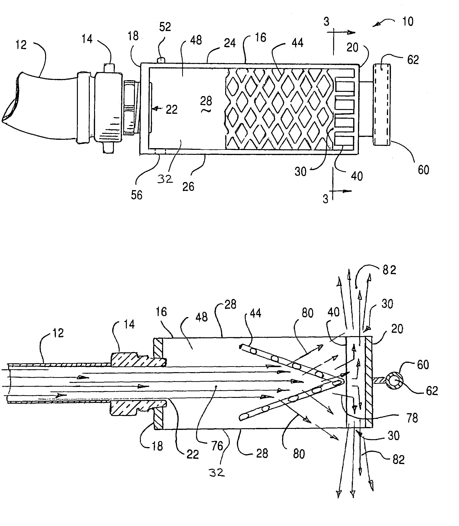
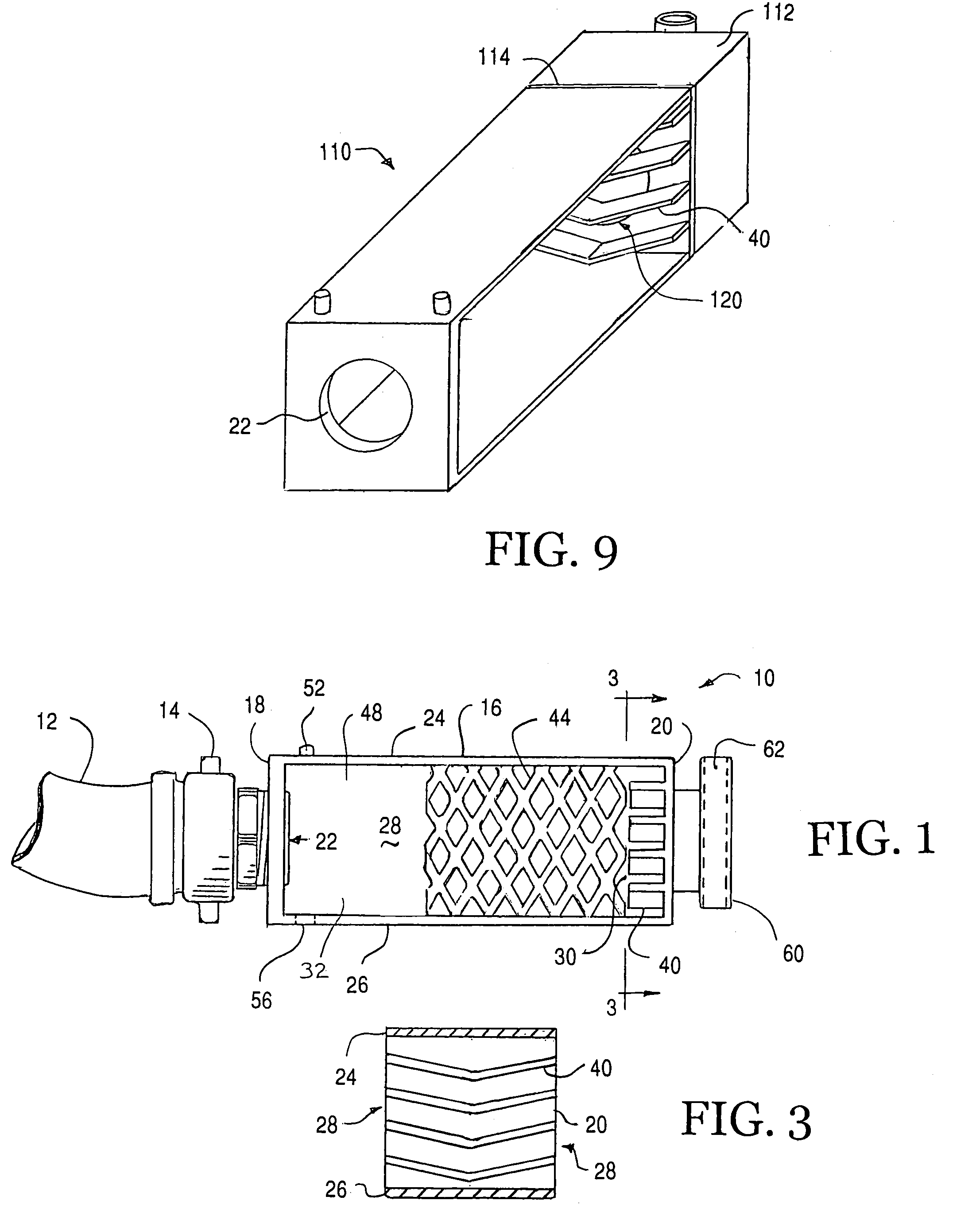
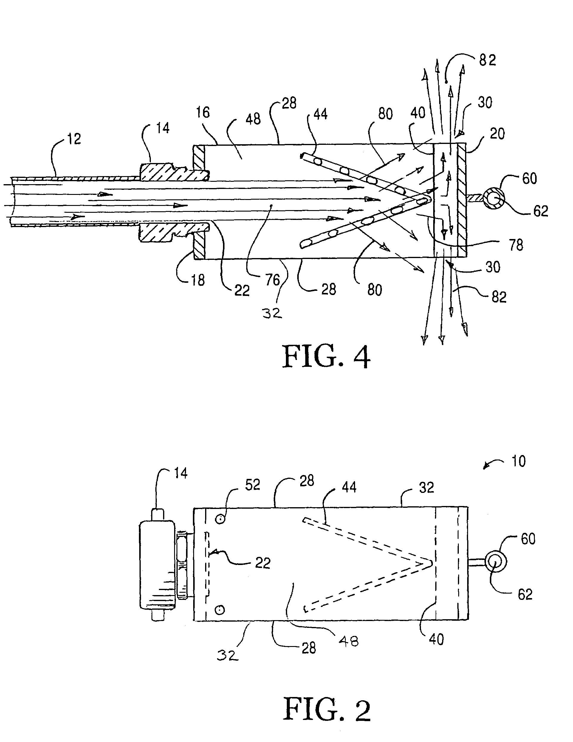
[0029]Referring now to the drawings, the preferred embodiments of the apparatus and method for the flow diverter of the claimed invention are illustrated in FIGS. 1 through 9. More particularly, FIG. 1 is a side view of the preferred embodiment of the flow diverter of the invention in which preferred flow diverter is designated generally by reference numeral 10. As shown in FIG. 1, the preferred flow diverter 10 is adapted to be connected to a source of pressurized fluid such as hose 12 by a suitable connecting device such as swivel hose connector 14. The preferred hose 12 is connected to a high-pressure fluid system (not shown) such as a fire hydrant, a fire pump or the like to be tested. The preferred hose 12 is adapted to convey an initial flow stream of pressurized fluid to flow diverter 10. The preferred flow diverter 10 is adapted to divert the initial flow stream of pressurized fluid from the source of pressurized fluid.

[0030]Referring still to FIG. 1, the preferred flow dive...


PUM


Abstract

A flow diverter for diverting an initial flow stream of pressurized fluid from a source of pressurized fluid. The flow diverter comprises a housing having an upstream end, an inlet opening in the upstream end, a downstream end generally opposed to the upstream end, a top plate extending between the upstream end and the downstream end, a bottom plate generally opposed to the top plate and extending between the upstream end and the downstream end, and a pair of generally opposed lateral sides extending between the upstream end, the downstream end, the top plate and the bottom plate. The upstream end is adapted to be attached to the source of pressurized fluid and the inlet opening is adapted to receive the initial flow stream of pressurized fluid from the source of pressurized fluid. The downstream end is adapted to divert the initial flow stream of pressurized fluid toward the pair of generally opposed lateral sides. The pair of generally opposed lateral sides are adapted to permit the initial flow stream of pressurized fluid to exit the housing in a pair of generally opposed diverted flow streams of pressurized fluid that are substantially perpendicular to the initial flow stream of pressurized fluid. The pair of generally opposed lateral sides are also adapted to permit the measurement of the initial flow stream of pressurized fluid.

Description

FIELD OF THE INVENTION[0001]The invention relates generally to devices and methods for diverting fluid flow, and particularly to devices and methods for diverting water flow in fire hydrants, fire pumps and the like.BACKGROUND AND DESCRIPTION OF THE PRIOR ART[0002]Water supply systems frequently require testing and purging to comply with local ordinances, operational requirements or safety codes. A perfect example is testing of fire hydrants. Regular testing and purging is required. Fire pumps installed in buildings for fire protection systems also require annual flow testing to meet with fire and safety code requirements.[0003]To test a typical system, temporary hoses are attached to an available connection and the water is released. A playpipe or flow diverter is connected to the end of the hose to allow flow measurements at the exiting water stream. A measurement device, typically a Pitot tube, determines the flow of exiting water. The water is often discharged in the immediate v...

Claims


Application Information

Patent Timeline
Patent Type & Authority Patents(United States)
IPC IPC(8): B05B1/26B05B17/00
CPCB05B1/267
Inventor LACROSSE, WILLIAM R.
Owner LACROSSE WILLIAM R
Why Eureka
Try Eureka