
Road wheel for tracked vehicles

a technology for tracked vehicles and wheels, applied in mechanical devices, transportation and packaging, hoisting equipment, etc., can solve the problems of high radial and lateral forces, high stress and strain on road wheels, and road wheels of higher weight and/or cost, so as to increase lateral and lateral strength, light weight, and the effect of reducing costs

Inactive Publication Date: 2006-11-21
GSE TECH
View PDF28 Cites 38 Cited by
  • Summary
  • Abstract
  • Description
  • Claims
  • Application Information

AI Technical Summary

Benefits of technology

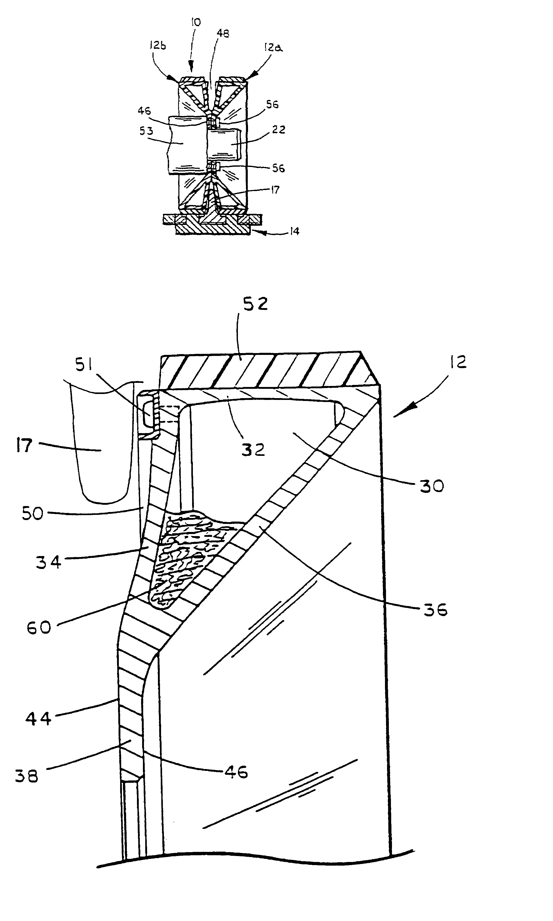
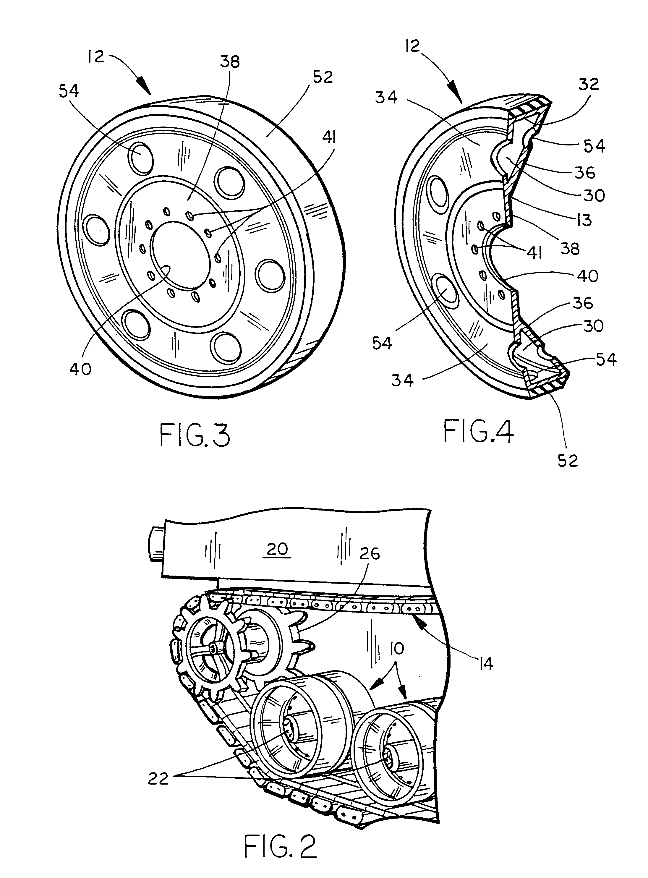
[0010]A hollow-shell road wheel for tracked-vehicles according to another aspect of the invention includes a circumferential cavity formed by an outer rim and two wall members that extend radially inward to a flange at approximately the mid-radius point of the hollow-shell road wheel. The cavity increases the radial and lateral strength, enabling use of thinner rim, flange, and wall members, which in turn reduces the weight of the hollow-shell road wheel. The cavity also enables use of less costly, lower strength materials without compromising function of the hollow-shell road wheel.
[0012]The cavity design of the hollow-shell road wheel increases its lateral and radial strength, thereby allowing use of lighter weight, lower cost alternative materials as compared to traditional road wheels, while still meeting stress, strain, and safety factor requirements. Additionally, the cavity design provides a more durable road wheel for tracked-vehicles. The lower cost, lighter weight, and increased durability of the hollow-shell road wheel improves the performance and lowers the cost of tracked-vehicles utilizing such wheels. Further, the road wheel of the present invention is self-cleaning because the closed nature of the circumferential cavity prevents the buildup of mud and debris as occurs with conventional wheel designs.

Problems solved by technology

Due to the weight of the tracked vehicles and the environments in which they are operated, these road wheels are subjected to high radial and lateral forces.
When the vehicle is turning or traversing a slope at an angle, the lateral forces create particularly high stresses and strains on the road wheels.
This, in turn, results in road wheels of higher weight and / or cost.
Additionally, as financial resources are always limited regardless of the application in which the tracked-vehicle is operating, there is a strong motivation and emphasis to reduce costs without compromising the safety and ability of such vehicles.
As such, road wheels of relatively high cost are not desired.

Method used


Image

  • Road wheel for tracked vehicles
  • Road wheel for tracked vehicles
  • Road wheel for tracked vehicles

Examples


Embodiment Construction

[0022]The present invention is embodied in a road wheel for tracked-vehicles. In particular, the preferred embodiment of the present invention is intended for the military AAAV vehicle. However, the invention is readily applicable to the road wheels of any tracked-vehicle.

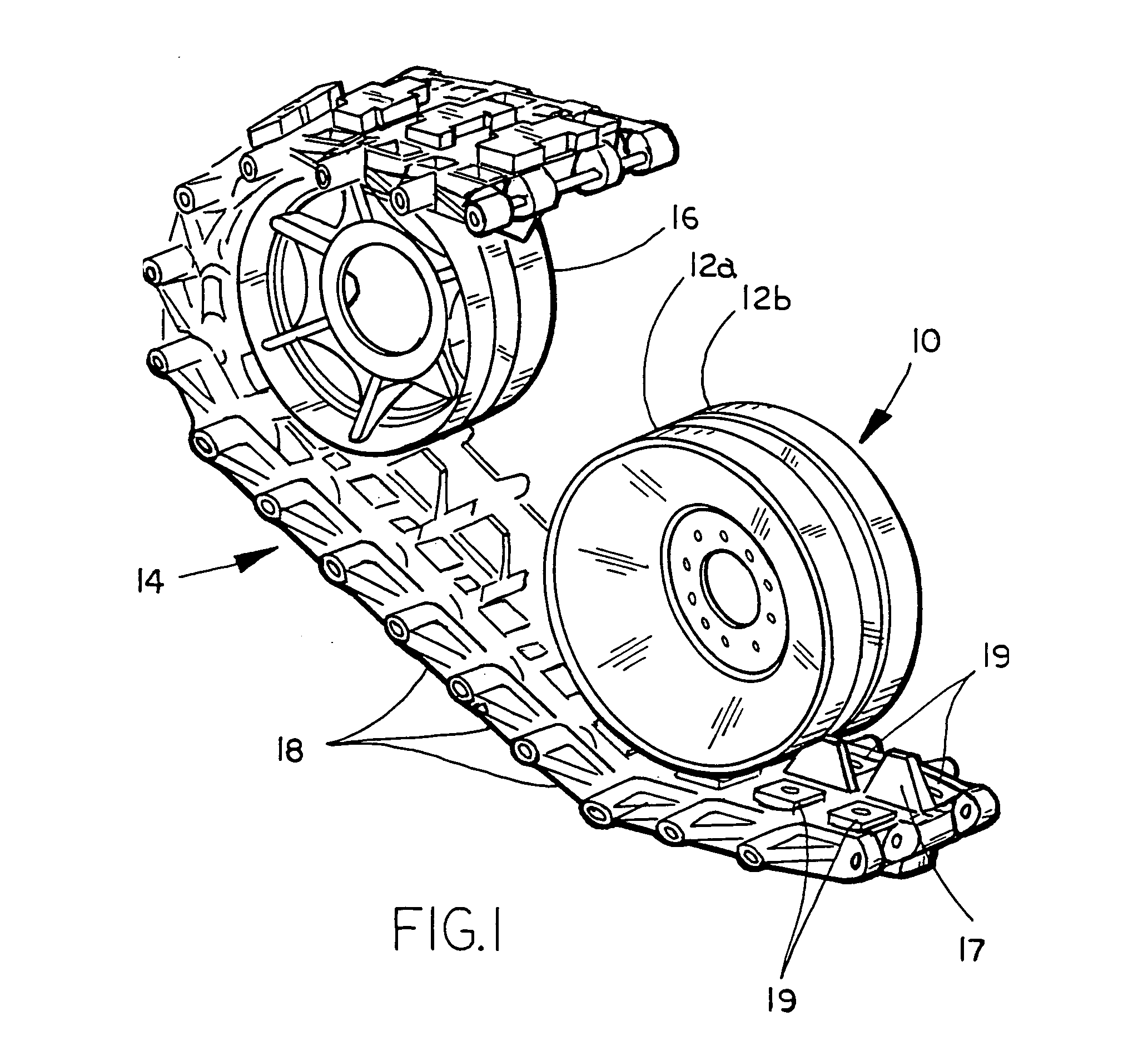
[0023]A preferred embodiment of the present invention can be seen in application in FIG. 1 as hollow-shell road wheel assembly 10. Assembly 10 includes an outwardly mounted, hollow-shell, road wheel 12a affixed to an identical, inwardly mounted, hollow-shell, road wheel 12b. In FIG. 1, hollow-shell road wheel assembly 10 is shown in relation to a portion of a track 14 of a tracked-vehicle and spoked wheel 16, where spoked wheel 16 may be either associated with a drive sprocket or a track tensioner. On the AAAV, the drive sprocket is forwardly mounted and the tensioner is rearwardly mounted. However, on other types of tracked vehicles, the tensioner may be located in the front and the drive sprocket in the rear. As ...


PUM


Abstract

A hollow-shell road wheel for tracked vehicles includes a generally triangular, outer circumferential cavity formed by an outer rim and two wall members that extend radially inward at angles to a generally planar flange at approximately the mid-radius point of the hollow-shell road wheel. A series of hollow-shell road wheels assembled in a back-to-back configuration support the tracked-vehicle and act as guides for the track of the tracked-vehicle.

Description

[0001]The present application claims benefit of U.S. provisional application Ser. No. 60 / 504,531, filed Sep. 19, 2003, which is herein incorporated by reference in its entirety.BACKGROUND AND TECHNICAL FIELD OF THE INVENTION[0002]The present invention is directed to wheels for supporting tracked-vehicles and, in particular, to the road wheels for tracked-vehicles that provide a rolling interface and support structure between the track and body of the vehicle.[0003]Tracked-vehicles are a superior means of traversing varied off-road surfaces compared to vehicles equipped with conventional pneumatic tires. The tracks provide an increased driving surface and area of contact with the ground thereby enabling superior support of heavier vehicles on such varied terrain. In addition, tracks are more durable than conventional tires such that they are less susceptible to puncture by sharp or metallic objects.[0004]Tracked-vehicles are utilized in military, forestry, and construction fields. Mi...

Claims


Application Information

Patent Timeline
IPC IPC(8): B62D55/12B60B23/00
CPCB62D55/0966B62D55/12B62D55/14B33Y80/00
Inventor SIMULA, GLEN RTARNOWSKI, STEVEN JJOHNSON, ADAM C
Owner GSE TECH
Learn More