Thermally loaded component

a technology of components and components, applied in the direction of manufacturing tools, machines/engines, mechanical equipment, etc., can solve the problems of difficult casting production, high cost, and high cost, and achieve the effect of efficient cooling

Inactive Publication Date: 2006-11-21
ANSALDO ENERGIA IP UK LTD
View PDF34 Cites 22 Cited by
  • Summary
  • Abstract
  • Description
  • Claims
  • Application Information

AI Technical Summary

Benefits of technology

[0007]The invention is related to a thermally loaded component with at least one cooling passage of the type described in the introduction, and avoiding problems with previously known means for diverting the cooling fluid yet at the same time allowing efficient cooling to be achieved.
[0009]Advantageously, the configuration of the diverter device according to the invention means that the functioning of the diverter device is not impaired compared to previously known diverter blades. The primary function of the diverter device, that of preventing pressure losses and avoiding separation of the cooling fluid stream downstream of the diverter passage, continues to be guaranteed.
[0010]Dividing the diverter device into two diverter parts that are spaced apart from one another avoids stresses and cracks that have been detected in blades and vanes that have been disclosed hitherto. Furthermore, the service life of the blades or vanes has been improved with regard to thermomechanical fatigue (TMF).

Problems solved by technology

However, these diverter blades are very fragile and are difficult to produce by casting, even in the case of large components, such as for example large blades or vanes of stationary gas turbines.
In some cases, these stresses may cause cracks to occur in the inner structures, with the result that the casting cannot be used.
If the defects are not noticed, the casting may break in use and may then, for example in the case of blades or vanes, cause damage to further blades or vanes and the turbine.

Method used


Image

  • Thermally loaded component
  • Thermally loaded component
  • Thermally loaded component

Examples


Embodiment Construction

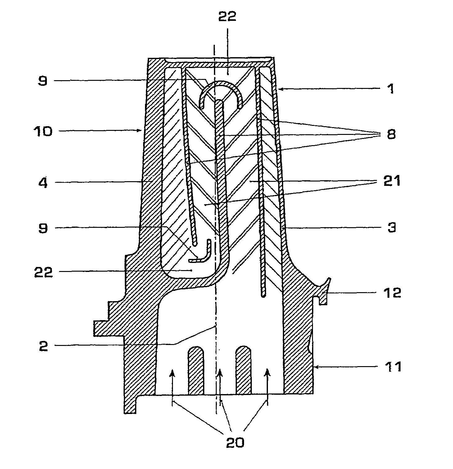
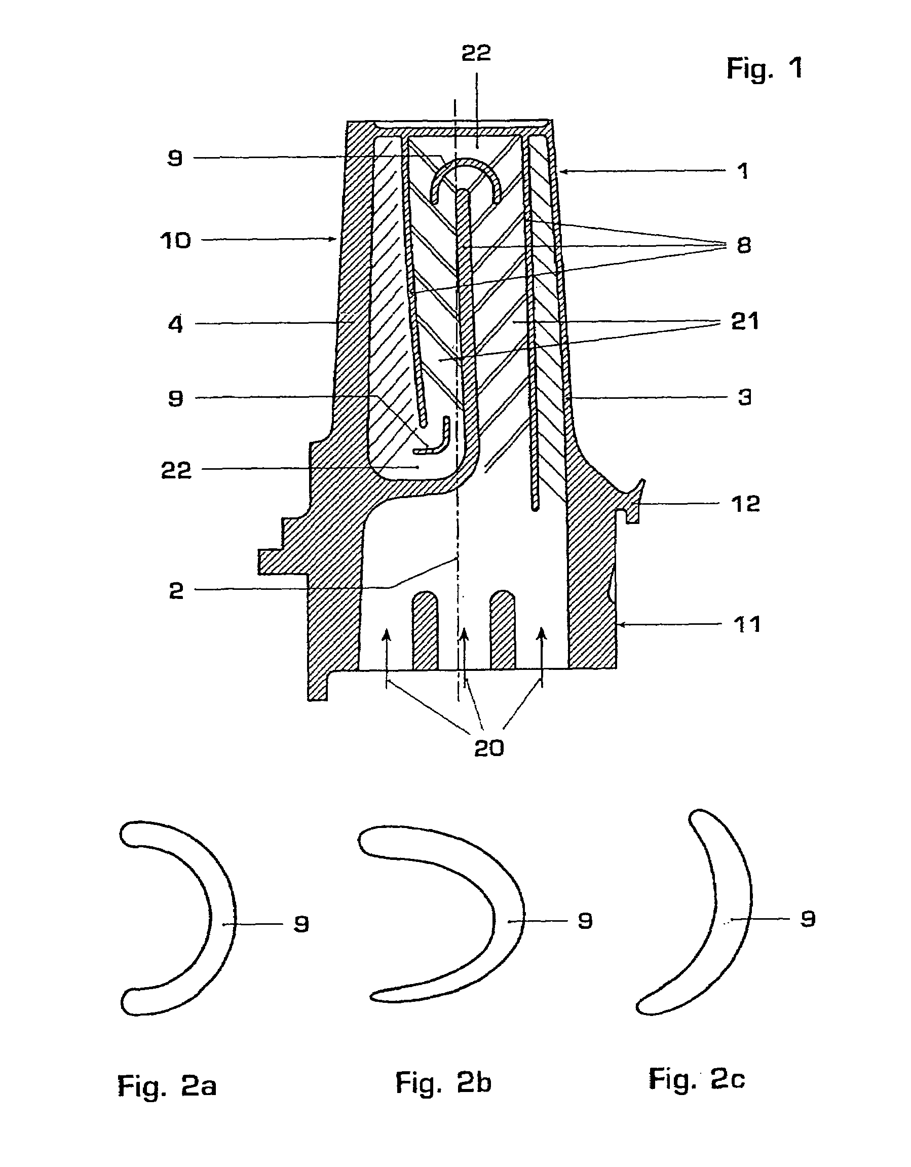
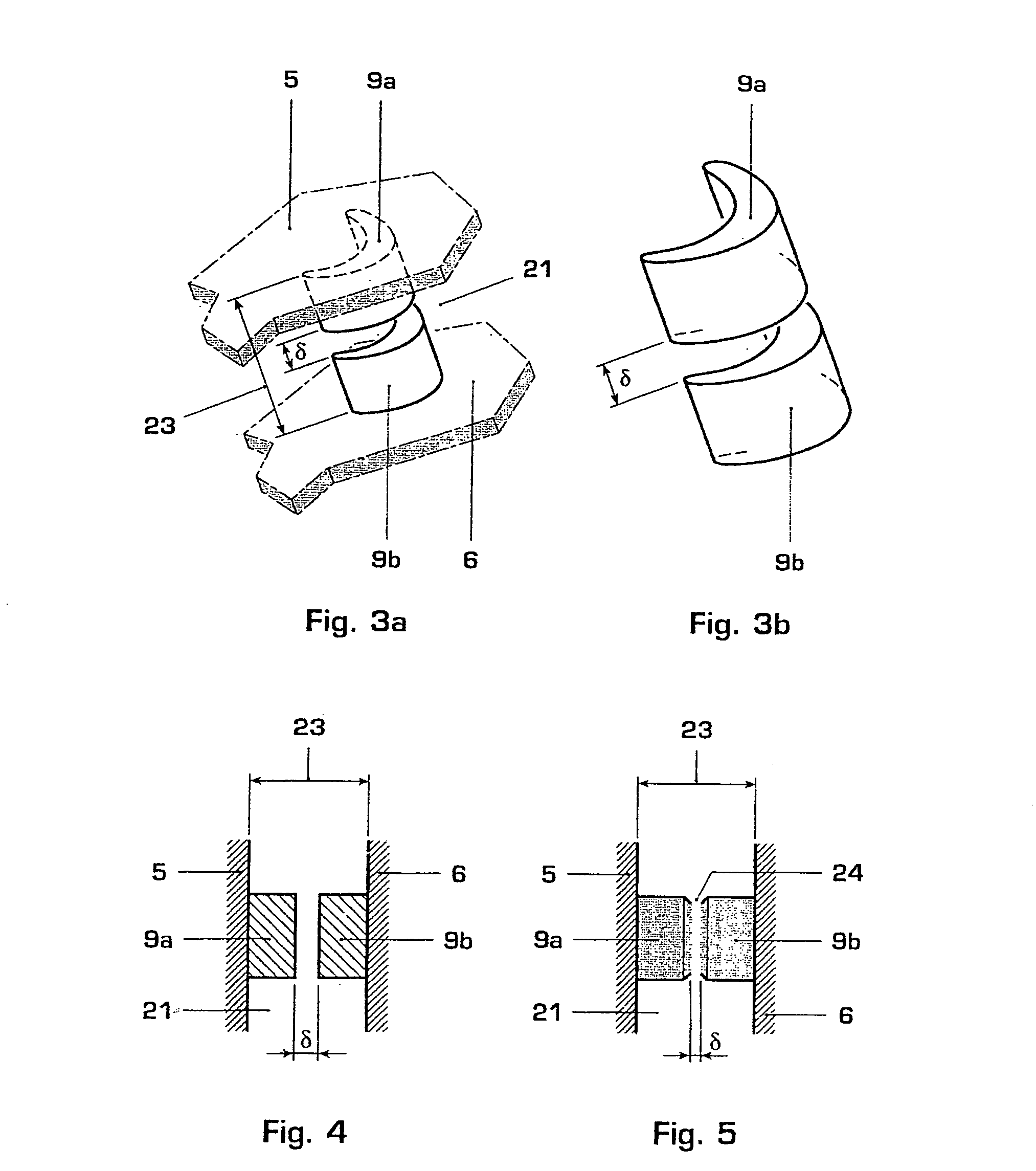
[0019]FIG. 1 shows a blade or vane 10 of a turbomachine, comprising a main blade or vane part 1 and a blade or vane root 11, by means of which the blade or vane 10 can be mounted on a rotor or stator (not shown). A platform 12, which shields the blade root and therefore the rotor or stator from the fluids flowing around the main blade or vane part, is usually arranged between the main blade or vane part 1 and the blade or vane root 11. The main blade or vane part 1 has a leading-edge region 3, a trailing-edge region 4, a suction-side wall 5 and a pressure-side wall 6 (cf. FIG. 3a), with the suction-side wall and the pressure-side wall being connected to one another in the region of the leading edge 3 and the trailing edge 4, so that a cavity 2 is formed. The leading-edge region 3 is in each case the region which is acted on first of all by the fluids flowing around the main blade or vane part 1. The cavity 2 runs substantially in the radial direction through the blade or vane 10 and...


PUM

PropertyMeasurementUnit
heightaaaaaaaaaa
shapeaaaaaaaaaa
pressureaaaaaaaaaa

Abstract

A thermally loaded component has at least one cooling passage for the flow of a cooling fluid passing through it. In the region of a bend, at least one diverter device for the integral capturing of the flow of the cooling fluid is provided within the cooling passage. The diverter device comprises, over the height of the cooling passage, two diverter parts which are spaced apart from one another. The diverter maybe cast with a notch therein so that during cooling, the diverter breaks into separated portions proximate the notch.

Description

CROSS-REFERENCE TO RELATED APPLICATIONS[0001]This application is a continuation of the U.S. National Stage designation of co-pending International Patent Application PCT / CH02 / 00661 filed Dec. 4, 2002, the entire content of which is expressly incorporated herein by reference thereto.FIELD OF THE INVENTION[0002]The invention is related to a thermally loaded component.BACKGROUND OF THE INVENTION[0003]An increase in the efficiency of a thermal power machine, e.g. a gas turbine, is directly dependent on an increase in the working temperature of the thermally loaded components and therefore, in the case of a gas turbine, on the combustion gas temperature of the combustion chamber and the turbine which follows it. Despite improvements in materials which are able to withstand high temperatures, cooling technology also needs to be improved in order to keep the materials temperature within a safe range when thermally loaded components of this type are in operation. Cooling passages are used f...

Claims


Application Information

Patent Timeline
Patent Type & Authority Patents(United States)
IPC IPC(8): F01D5/18
CPCF01D5/187Y10T29/49341Y10T29/49989
Inventor HALL, KENNETHPARNEIX, SACHATSCHUOR, REMIGI
Owner ANSALDO ENERGIA IP UK LTD
Why Eureka
Try Eureka